Download
1 / 59
620 likes | 976 Views
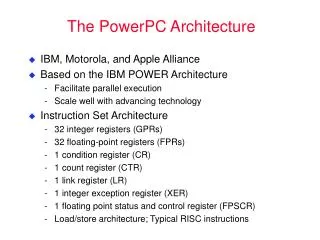
PowerPC. PowerPC family. PowerPC is a family of processors 601, 603, 604, 620, 750 Each processor has the same architecture , but different organization same instruction set different performance levels Joint development effort IBM, Motorola, Apple RISC based architecture.

E N D
PowerPC family • PowerPC is a family of processors • 601, 603, 604, 620, 750 • Each processor has the same architecture, but different organization • same instruction set • different performance levels • Joint development effort IBM, Motorola, Apple • RISC based architecture
Instruction unit instructions instructions Cache main memory PowerPC organization Floating-point unit Integer unit
Registers Load/Store Unit Data Cache MMU Instr. Cache FPU
FR0 floating - point registers FR31 R0 general- purpose registers R31 condition register CR XER integer exception register PowerPC registers
Special registers link register LR count register CTR PC program counter
Addressable data units Bit 0 63 byte 0 byte 7 Half word 0 Half word 2 Word 0 Word 2 Double word 0
Memory • Memory is byte addressable • Half words always have even addresses • Words always have addresses that are a multiple of 4 • Default mode (when power is switched on) is big-endian scheme
Instructions • All instructions are 32 bit • Five type of instructions • Load/Store instructions • Integerarithmetic and logic instructions • Flow control • Floating-point instructions • Processor control instructions • Format: INSTR Rdst, Rsrc
Load/Store • Format: Load Rdst, Rsrc • Format: Store Rsrc, Rdst • Two addressing modes: • immediate index • register index
Immediate index • Immediate Index mode LHZ R0,x(R1)means [R0]0-15M([R1] + x); [R0]16-31 0 LHZ R0,x(0)means [R0]M(x ) where xis sign extended to 32 bit • L = Load • H = Half word • Z = Fill higher order 16 bits with 0’s
Register index • Register Index mode LHZX R0,R1,R2means [R0]M([R1] + [R2]) LHZX R0,0,R2means [R0]M([R2]) • The extra X in the instruction specifies that indexing is used
Example 300 541 1000 1012 R3 14 R4 0 300 0 541 R5 R5 LHZ R5,12(R3) LHZX R5,R3,R4 LHZ R5,14(R3) or
Update instructions • Index addressing can also be done in update mode • Update Index mode LHZU Rdst,x(Rsrc)means [Rdst]M(x+[Rsrc]); [Rsrc] x+ [Rsrc] • Similarly we have LHZUX Rdst,Rsrc1,Rsrc2
Store instructions • Store instructions have similar formats • Example STWU Rsrc, x(Rdst) means M(x + [Rdst])[Rsrc]; [Rdst] x+[Rdst]
Arithmetic instructions • May have two or three operands • Arithmetic instructions with register operands ADD Rdst,Rscr1,Rsrc2 meaning [Rdst] [Rsrc1] + [Rsrc2]
Immediate operands • Arithmetic instructions with immediate operands ADDI Rdst,Rsrc,x meaning [Rdst] [Rsrc] + x • Operand x must be extended to 32 bit
Shifted immediate operands • Used to specify constants • Instruction ADDIS is similar to ADDI, but places result into higher order half of word and leaves lower half unchanged • Together they can specify 32 bit constants ADDI R2,0,$15EA ADDIS R2,0,$02AA places number 02AA15EA(hex) in R2
ADDI 15EA ADDIS 02AA 0000 15EA R2 02AA 15EA R2 Example
Summation example ADDI R3,0,SUML initialize R3 to point ADDIS R3,0,SUMH to location SUM ADD R4,0,R3 save address SUM in R4 ADDI R1,0,0 clear R1 LWZU R2,4(R3) [R2] N1; [R3] [R3]+4 ADD R1,R1,R2 compute partial sum LWZU R2,4(R3) [R2] N2; [R3] [R3]+4 ADD R1,R1,R2 compute partial sum ........ ....... LWZU R2,4(R3) [R2] Nn; [R3] [R3]+4 ADD R1,R1,R2 compute partial sum STW R1,0(R4) store sum
Condition codes(1) 31 0 1 2 3 LT GT EQ SO Condition Register (CR) 31 0 1 2 3 SO OV EQ CA Integer Exception Register (XER)
Condition Register • Condition register LT: Set ot 1 if result arithmetic operation is <0 GT: Set ot 1 if result arithmetic operation is >0 EQ: Set ot 1 if result arithmetic operation is =0 SO: Set ot 1 if result overflows
Integer exception register • Integer exception register SO: similar to SO bit in CR OV: arithmetic overflow CA: carry occurs in MSB • Difference between OV and SO is that SO remains set until cleared by special instruction
Condition control • Instructions can indicate whether or not condition bits are affected • This is done by adding one of the suffixes “.”, “o”, or “.o” • Example: ADD.,ADDo,orADD.o • “.” indicates set CR • “o” indicates set XER
LT GT Example LHZ R2, 5(0) LHZ R3, 3(0) ADD. R1,R2,R3 SUBF R1,R2,R3 SUBF. R1,R2,R3 ADD R1,R2,R3 [R1] 8 , CR = 0100 [R1] -2, CR = 0100 [R1] -2, CR = 1000 [R1] 8, CR = 1000
Flow control • Two basic branch instructions: • B Branch unconditionally • BC Branch if condition is satisfied
Branch address modes • There are three branch address modes: • Relative: distance between branch instruction and target address is given • Absolute: absolute target address is given • Register indirect: target address is given in one of the following registers • Link register • Counter register
Branch relative • Branch relative loc: B ta • Displacement address is da = ta - loc and is stored in instruction by assembler as ida = da*2-2 • At branch the target address is calculated [PC] [PC] + signextend(ida *22)
Question • What is the purpose of the multiplication by 2-2 and 22 ,respectively ?
Branch absolute • Branch absolute loc: BA ta means [PC] ta • Branch registers BLR means [PC] [LR] BCTR means [PC] [CTR]
Conditional branching • PowerPC has large number of conditional branch instructions • Some instructions test more than one condition • Some branch if relevant CR bit is 1, some if relevant CR bit is 0
Some conditions ConditionFlag Relative Absol. < LT=1 BLT BLTA <= GT=0 BLE BLEA = EQ=1 BEQ BEQA >= LT=0 BGE BGEA > GT=1 BGT BGTA /= EQ=0 BNE BNEA
Example ADDI R3, 0, SUML initialize R3 to point ADDIS R3, 0, SUMH to location SUM ADD R4, 0, R3 save addr. SUM in R4 LWZU R5, 4(R3) n in R5; [R3] [R3]+4 ADDI R1, 0, 0 init SUM to 0 L LWZU R2, 4(R3) Load entry; [R3] [R3]+4 ADD R1, R1, R2 compute partial sum ADDI. R5, R5, -1 decrement counter BGT L loop if >0 STW R1, 0(R4) store sum
Counter register • Counter register is used to control program loops • Decrements counter and tests in single instruction BDNZ L • Special instructions to access counter contents MTCTR Rsrc MFCTR Rdst
Example use ..... ..... MTCTR R5 load counter register L LWZU R2, 4(R3) Load entry; [R3] [R3]+4 ADD R1, R1, R2 compute partial sum BDNZ L decrement and loop if >0 .......
Compare • Used to compare values and leave register contents unchanged • Compare instructions can use any of the eight4 bit CR fields: CMPW CRi, Rsrc1, Rsrc2 CMPWI CRi, Rsrc, x • example CMPWI CR3, R2, 10 BGT CR3, 2000
CR organization CR0 CR1 CR2 CR3 CR4 CR5 CR6 CR7 LT GT EQ SO
Sorting example int[] listarray = new list[n]; int temp; for(j=0, j<n-1, j++){ for(k=j+1, k<n, k++){ if(list[j] > list[k]) { temp = list[j]; list[j] = list[k]; list[k] = temp; } } }
Assembler code Assume R1 contains the address of List[0] ADDI R2, 0, 0 [R2] 0 (init j) outer ADDI R3, R2 ,1 [R3] j+1(init k) SUBFI R4, R3, n MTCTR R4 [CTR] n-j-1 inner LBZX R4, (R1,R2) [R4] list[j] LBZX R5, (R1,R3) [R5] list[k] CMPW CR1, R4, R5 BLE CR1, next if list[j]>list[k] STB R4, R1, R3 swap STB R5, R1, R2 next ADDI R3, R3, 1 increment k BDNZ inner decrement and test ADDI R2, R2, 1 increment j CMPWI CR1, R2, n-2 BLE CR1, outer repeat if jn-2
Question • Why is the assembler program not a correct translation of the Java program?
Logic instructions • Logic operations • AND, OR, XOR • Various shift and rotate instructions • SRW, SRAW, SRWI
Multiple CR fields • There are special instructions for performing logic operations on bits of the CR register CRAND CRBi,CRBj,CRBk means Bit(i) Bit(j) & Bit(k)
Example CRAND CRB14,CRB5,CRB8 CR0 CR1 CR2 CR3 CR4 CR5 CR6 CR7 LT GT EQ SO GT LT &
Example if( (A>B)&&(C<D) ){ <do something> } condition statement Compare A,B Branch if not > next Compare C,D Branch if not < next <do something> next ..... pseudo conventional assembler
Use of CR CMPW CR1, R1, R2 CMPW CR2, R3, R4 CRAND CRB14, CRB5, CRB8 BNE CR3, next <do something> next .....
Subroutines • No separate subroutine call in PowerPC • Any branch instruction can specify that return address is saved in Link register • Done by adding L to branch instruction examples: loc: BL ta means [PC] ta; [LR] loc+4 • Return is BLR(meaning [PC] [LR])
Other variations • Examples: loc: BLTL ta means if <0 then [PC] ta, else [PC] [PC] +4; [LR] [PC] +4 loc: BGTCTRL means if >0 then [PC] [CTR], else [PC] [PC] +4; [LR] [PC] +4
Stack frames .... LWZ R20,X(R15) Load parameter in R20 2000 BL Sub1 Call subroutine at 2400 ........... Stack 10052 R1 Stack Pointer 2004 Link 2400 PC 10052 Sub1 starts at address 2400
Subroutine Sub1 2400 ADDI R1, R1, -16 Create stack frame STMW R29, 4(R1) Save R29-R31 MFLR R29 return in R29 STW R29, 0(R1) copy to stack frame .... LWZ R29, Y(R30) Load par. in R29 2432 BL Sub2 Call subroutine ........... at address 2500 LWZ R29, 0(R1) Restore Link reg. MTLR R29 LMW R29, 4(R1) Restore registers ADDI R1, R1, 16 remove stack frame BLR return