Download
1 / 20
200 likes | 292 Views
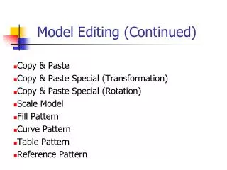
TUTORIAL 3 MODEL EDITING. Table of Contents. Section Page Step1. Open MSC.Sofy Database . 3 Step2. Change Part Color. 4 Step3. Create Curves on an existing Mesh. 6 Step4. Edit Mesh To Follow Geometry. 9 Step5. Explore Extended Pick Dialog Options. 12

E N D
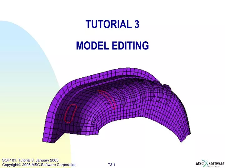
TUTORIAL 3 MODEL EDITING
Table of Contents SectionPage Step1.Open MSC.Sofy Database .3 Step2. Change Part Color. 4 Step3.Create Curves on an existing Mesh.6 Step4. Edit Mesh To Follow Geometry. 9 Step5. Explore Extended Pick Dialog Options. 12 Step6. Create Bead By Moving Center Nodes. 16 Note: All menu items that need to be selected will be preceded by a maroon right arrow: >User action. Mouse buttons are indicated as follows: -- 1B = First (left) button -- used for selecting items -- 2B = Second (middle) button -- used for "OK" -- 3B = Third (right) button -- used for View Manipulation & pop-up menus Normally 1B is used, unless otherwise noted. You will be creating the curves as shown in red in the following figure. The curve on the left is for a hole and that on the right is for a bead.
Step1. Open MSC.Sofy Database . • Select> File Menu >Open SOFY DB - to open an existing tutorial database. • In the file dialog box - goto the directory (in your home directory) >SOFY3.0/SOFY_MASTER2/DEMOS/Tutorials_Basic/ open >tutor03_ModelEdit.sof. The model should appear a shown. • Get a closer look -- CVP- View Menu >Bead-Hole (pre-defined view) • Create a new part - LINES Top Bar >Edit >Create >Part. b d
Step2. Change Part Color. Change the colors of the parts: • Top Bar >Part Menu >Change Color. • Select the part >WHINR on the screen or on the Collection menu. • Click >Done in Pick menu. • SelectRed color from color chart. • In the same way, change the color of the new part LINES to light green . a b d
Step2. Change Part Color. (Cont’d) f f. Change the Edge color to Part colorBottom Block >Geom-Grafix >(Edge Color) Part Color g. Change the Graphics to Wire-frame.Bottom Block >FE-Grafix >WireFrame g
Step3. Create Curves on an existing Mesh. a • Make LINES the Current Part.Collection Menu >Click(2B)> LINES Recall that (2B) means select with the second mouse button. • Get the proper view to create a hole.View Block >Hole • Select >Edit >Create >Geometry >Arc/Circle • Pick Menu >Pt. on Element. b d c
Step3. Create Curves on an existing Mesh. (Cont’d) f • Select >D (Extended Pick Dialog, or EPD) on left side of Pick Menu. • In the EPD dialog box, right side, select >@ Centroid. Leave this menu open until finished Picking points; otherwise the default mode - @ Cursor will get activated. Now, you are ready to start. • Select the first location of the 3 point arc – 1. Select >element (and consequently its centroid ) as shown below. 2. Select the >elementone column to the right and one row below. 3. Then Select the >elementone column to the right and one row ABOVE. • An arc is created. You can use >R. Last (in Pick menu) to reject your selections or most recent operations. g
Step3. Create Curves on an existing Mesh. (Cont’d) n Now, to continue making the 3 Pt. arcs... • In the Pick menu >Pt. on Element should still be selected, • Extended Pick Dialog >@ Centroid should still be activated. • Now select the >last element that was picked (step n). • Then Select the >element one row above. • Then Select the >element one row above (again). • This will form a larger radius arc for the side of the hole. • Similarly, create the semi-circular arc on the top and the arc on the left to complete the slotted hole. You can use >R. Last to reject your selections or most recent operations. v u
Step4. Edit Mesh To Follow Geometry. Create semi circular arc: a. From Top Bar >Element >Split. b. Pick Menu >Curves c. Select the >lower semi-circular arc. d. Then - Select the >curve on the right. e. Continue around the hole, selecting the >upper semi-circular arc . >curve on the left. b a e c
Note: The split element command splits all displayed elements that come in the path of the selected curves Step4. Edit Mesh To Follow Geometry. (Cont’d) f. Pick menu: >Done. Remember: You can use >R. Last to reject your selections or most recent operations. g. ViewMenu >Plot h. Top Bar >Edit >Delete FEM. In Pick block>change pick type to >Elements. h f
Step4. Edit Mesh To Follow Geometry. (Cont’d) i. Tool Bar> Pick Styles menu>Sketch picking mode j. By holding down the 1B - sketch a closed loop around all elements inside the hole. k. With mouse still inside canvas, click >2B to confirm. (Same as: Pick block, >Done ). l. Click >Exit on Pick block to exit the Delete command. m. Push function key >F4. (Clear Unreferenced Nodes.) n. View block >Bead-Hole i n
Step5.Explore Extended Pick Dialog Options. Let’s Create Bead: a. View Block >Bead. b. A curve will be created using different selection modes. Top bar >Edit >Create >Geometry >Create Polyline/ Spline. c. On pick block> select >Pt on Element. MSC.SOFY can pick the exact center of the element's edge. d. Pick Menu >D ( to open the Extended Pick Dialog EPD). e. Now in the EPD, right side, "Pt. On Element Type" -- select >On Edge @ Center. (Do not close the EPD yet.) b c e d
Step5.Explore Extended Pick Dialog Options. (Cont’d) f f. Pick the >edge of the element as shown in the figure below. A location on the center of the edge will be automatically highlighted. g. Next Pick the edge - just below it -- continue until you have picked 10 edges. Now - we are going to change to picking Nodes: h. Pick Menu >Nodes i. Pick the node below and to the right of the last selection. j. Change the picking mode back to >Pt on Element. Make sure the "Pt. On Element Type" is still >On Edge @ Center. g
Step5.Explore Extended Pick Dialog Options. (Cont’d) • Next Pick the edge to the right and just above the last node that you had selected. -- Continue selecting edges above until you have picked 10 edges. • Again- we are going to change to picking Nodes: Pick Menu >Nodes • Pick the node above and to the left of the lastselection. • In the Pt. on Element Type pop-up select >Exit. • Select >Done in the pick menu to create the curve. • View Menu >Plot . o
The split element command splits all displayed elements that come in the path of the split line. Step5.Explore Extended Pick Dialog Options. (Cont’d) q. Top Bar >Element >Split r. Pick Menu: >Curves. s. Pick the >curve outlining the Bead. t. Select >Done from Pick menu u. View Menu >Plot . u r q
Step6.Create Bead By Moving Center Nodes. Now to create the bead by moving the center nodes. • Top bar> Node Menu >Move Node . • In Pick Menu> change >Loc. to Loc to >Along Node Normal. • We want to move the nodes .normal to the respective elements. • Select all the >nodes that are on the Bead Center, as in the animation. Remember: You can use >R.Last to reject your most recent selections. e. Now confirm with >2B. (Or, Pick menu: >D - Done). f. In the Offset pop-up enter >12-- then >Ok. a b f
Step6.Create Bead By Moving Center Nodes. (Cont’d) g • Bottom Block >FE-Grafix >Fill+Edges • View Block >Bead-Hole • View Menu >Plot • Turn off the part - LINES: Collection block >(1B) LINES (un-check box) • View block: >Plot • From top bar >Display >Highlight FE Boundary • View block: >Cl Hghlts • View block: >Fill • To QUIT: Top-Bar >File >Quit. Don't Save. h m l
Congratulations! You have just completed Tutorial 3!!