Download
1 / 11
130 likes | 306 Views
Tutorial 3. CUFSM 3.12. LGSI Zee in Bending: Z 12 x 2.5 14g, F y = 50ksi Objective To model a typical Zee purlin or girt in bending and determine the elastic critical local buckling moment (M cr l )and elastic critical distortional buckling moment (M crd ).

E N D
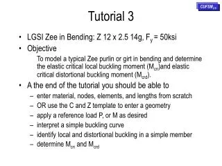
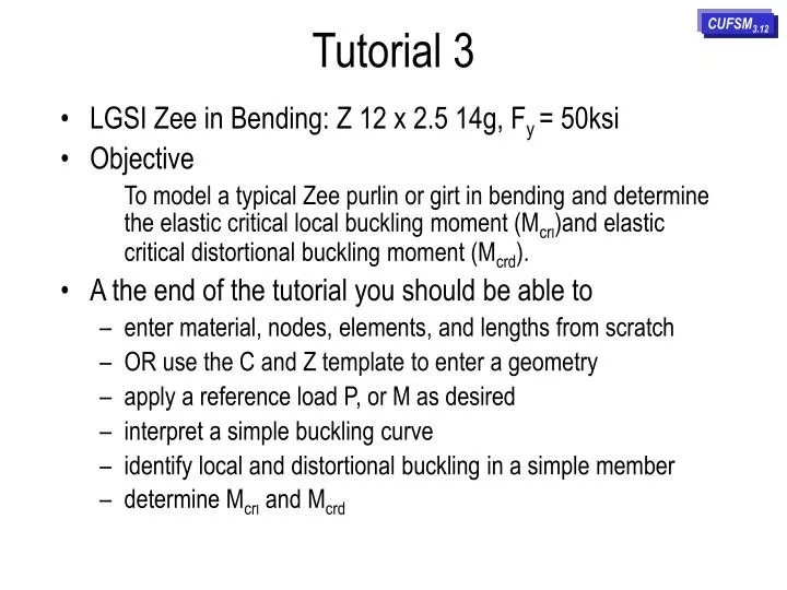
Tutorial 3 CUFSM3.12 • LGSI Zee in Bending: Z 12 x 2.5 14g, Fy = 50ksi • Objective To model a typical Zee purlin or girt in bending and determine the elastic critical local buckling moment (Mcrl)and elastic critical distortional buckling moment (Mcrd). • A the end of the tutorial you should be able to • enter material, nodes, elements, and lengths from scratch • OR use the C and Z template to enter a geometry • apply a reference load P, or M as desired • interpret a simple buckling curve • identify local and distortional buckling in a simple member • determine Mcrl and Mcrd
2.SELECT 1. SELECT
This screen shows the default section that appears when you enter the Input screen for the first time. In our case we do not want to use this section so we need to start from scratch in order to enter our LGSI Z 12x2.5 14g purlin. Select Note, we could enter the geometry node by node as in Tutorial #2, but in this case, let’s use the template instead. Select C/Z template
This is the default template that comes up when you select the template button. Note that all dimensions are centerline dimensions - e.g., h is the flat distance, not the out-to-out distance as is typically listed in product catalogs, etc. Enter in all the appropriate dimensions and select Submit to input. The centerline dimensions for an LGSI Z 12 x 2.5 14g member are shown to the right. Enter in these dimensions and then press Update Plot. When complete select Submit to Input. Note, the material is assumed to be steel, but two units systems are supported. Geometry other than the typical Cee or Zee can be entered. The template automatically selects an adequate number of elements. The template automatically selects lengths to be analyzed as well.
SELECT This is the model generated by the template. It can be still be modified as desired. The default loading is 1.0 on every node, let’s go to the properties page and apply a pure bending stress distribution.
Note that the principal coordinate system is not in line with the global x,z coordinate system, as expected. Enter a yield stress, calculate P and M, uncheck P and examine the generated stress distribution. As shown to the right, it reflects unsymmetric bending. Switch to restrained bending and re-calculate the stress distribution.
1 2 select 1, analysis will proceed, then select 2 This is the yield moment, My, the buckling load factor results will be in terms of My=192 kip-in. The stress distribution to the right would be applicable for a laterally braced beam, and is typically assumed in cold-formed steel design codes. Note that the flanges are different sizes and in this case the wider flange has been placed in compression.
This screen shows the post-processing page that will come up when you select Post. Note, the two minima in the plot: local and distortional buckling. Clean up the curve and change the half-wavelength to show local buckling.
Local buckling results are shown here. Mcrl=0.66My and the buckling mode shape is as given to the right. Change the half-wavelength to examine distortional buckling.
Distortional buckling results are shown here. Mcrd=0.70My and the buckling mode shape is as given to the right.
Tutorial 3 CUFSM3.12 • LGSI Zee in Bending: Z 12 x 2.5 14g Fy = 50ksi • Objective To model a typical Zee purlin or girt in bending and determine the elastic critical local buckling moment (Mcrl)and elastic critical distortional buckling moment (Mcrd). • A the end of the tutorial you should be able to • enter material, nodes, elements, and lengths from scratch • OR use the C and Z template to enter a geometry • apply a reference load P, or M as desired • interpret a simple buckling curve • identify local and distortional buckling in a simple member • determine Mcrl and Mcrd