Download
1 / 18
180 likes | 388 Views
A/D Conversion and Interfacing. Physics 270. Voltmeters. Analog Voltmeter. Digital Voltmeter. Signal Scaler (attenuator amplifier) Digital conditioner (reduces scaled input signal to a DC voltage within range of A/D converter) A/D Converter Control Logic. Analog versus Digital.

E N D
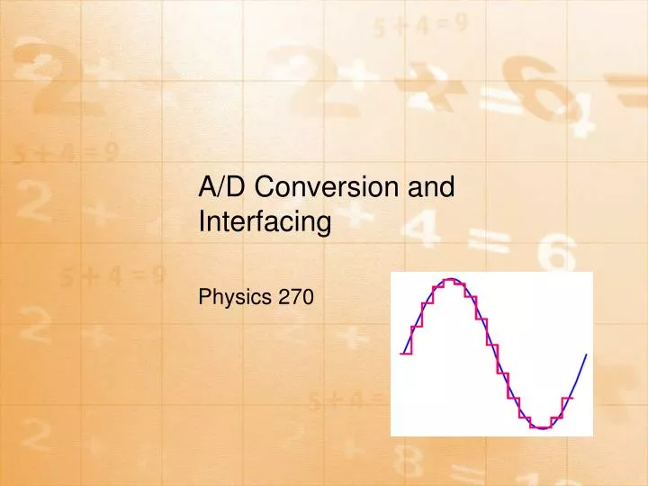
A/D Conversion and Interfacing Physics 270
Digital Voltmeter • Signal Scaler (attenuator amplifier) • Digital conditioner (reduces scaled input signal to a DC voltage within range of A/D converter) • A/D Converter • Control Logic
Analog versus Digital • Analog is continuous. • Digital is discrete. • A/D = analog to digital • D/A = digital to analog • Digital… base 2 system • Analog… base 10 system
Digital Representation How many bits would you need to divide 10 V into 0.01 V intervals? • If you divide 10 V into 0.01 V intervals you need 1000 intervals. • If you need 1000 intervals you need to think about a power of 2 that is larger than 1000. • The smallest power of 2 that is larger than 1000 is 210 which is equal to 1024. • That means that you need 10 bits in the converter, and then the count in the counter/register will run from 0 to 1023. • And that leads us to observe that real converters often go to 10.23 V, not 10V, because that gives perfect 0.01 V increments between resolvable voltages. • And another converter might run from -5.12v to +5.11v for the same reason.
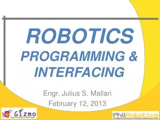
Gain Error Other sources of error Come from non-linearity, Missing bits, etc.
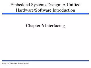
Current-Measurement Error To minimize the percentage error, an ammeter's input resistance should be less than the Thevenin resistance of the original circuit by 20 times or more. Conversely, a voltmeter should have an input resistance that is larger than the Thevenin resistance of the original circuit by more than 20 times. The same goes for the ohmmeter; it should have an input resistance that is at least 20 times the Thevenin resistance of the original circuit. By following these simple rules, it is possible to reduce the error to below 5 percent.
LabView • Number One Data Acquisition and Control Environment – used everywhere • Learning Curve • Labview Introduction Video • http://zone.ni.com/wv/app/doc/p/id/wv-411/nextonly/y