Download
1 / 68
680 likes | 864 Views
Chapter 2 Electic-ight conversion. 1. Light-emitting diode.

E N D
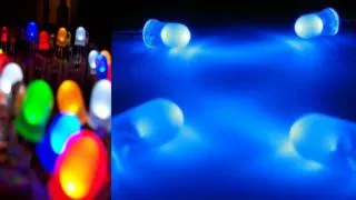
1. Light-emitting diode A light-emitting diode (LED) is a semiconductor light source.[3] LEDs are used as indicator lamps in many devices and are increasingly used for other lighting. Introduced as a practical electronic component in 1962,[4] early LEDs emitted low-intensity red light, but modern versions are available across the visible, ultraviolet, and infrared wavelengths, with very high brightness. Red, pure green and blue LEDs of the 5mm diffused type LED retrofit "bulb" with aluminium heatsink
History In 1961 American experimenters Robert Biard and Gary Pittman, working at Texas Instruments,[13] found that GaAs emitted infrared radiation when electric current was applied and received the patent for the infrared LED. The first practical visible-spectrum (red) LED was developed in 1962 by Nick Holonyak Jr., while working at General Electric Company.[4] Holonyak is seen as the "father of the light-emitting diode".[14] M. George Craford,[15] a former graduate student of Holonyak, invented the first yellow LED and improved the brightness of red and red-orange LEDs by a factor of ten in 1972
Types LEDs are produced in a variety of shapes and sizes. The 5 mm cylindrical package (red, fifth from the left) is the most common, estimated at 80% of world production. The color of the plastic lens is often the same as the actual color of light emitted, but not always. For instance, purple plastic is often used for infrared LEDs, and most blue devices have clear housings. There are also LEDs in surface-mount technology (SMT) packages, such as those found on blinkies and on cell phone keypads (not shown). The main types of LEDs are miniature, high power devices and custom designs such as alphanumeric or multi-color Different sized LEDs. 8 mm, 5 mm and 3 mm, with a wooden match-stick for scale A green surface-mount LED mounted on an Arduino circuit board
1. Light –Emitting Diodes (LEDs) Principle p-n junctionWe insert atoms of another material (called dopants) into a semiconductor so that either a majority of electrons (negative charge carriers) or a majority of holes (positive charge carriers) will be created. The former semiconductor is called the n type and the latter is called the p type. We call these n type and p type doped, or extrinsic, not a pure, or intrinsic.
When an n-type semiconductor is brought into physical contact with a p type, a p-n junction is created. At the boundary of the junction, electrons from the n side diffuse to the p side and recombine with holes and, at the same time, holes from the p side diffuse to the n side and recombine with electrons. An electron-hole recombination releases a quantum of energy—aphoton. In other words, to make a semiconductor radiate, it is necessary to sustain electron-hole recombinations.
Spontaneous radiation :Because the transition of electrons from many energy levels of conduction and valence bands contributes to the radiation produced, thus making the spectral width of such a source very wide.
LED: Principle of action The forward-biasing voltage, V, causes electrons and holes to enter p-n junction and recombine Alternatively, we can say that the external energy provided by V excites electrons at the conduction band. From there, they fall to the valence band and recombine with holes. Whatever point of view you prefer, the net result is light radiation by a semiconductor diode.
Electronic circuit; • An input-output characteristic.
Radiating wavelengths:A radiating wavelength is determined by the energy gap of a semiconductor
Rise/fail time is determined by an LED’s junction capacitance (C),which determine the frequency response or Bandwidthof LED.
Bit rate (BR) or data rate is the number of bits that can be transmitted per second over a channel, it is for digital transmission. Bandwidth (BW) is the frequency range within which a signal can be transmitted without significant deterioration .it is for analog transmission(Hz).Bit rate(BR) and bandwidth(BW) are the direct measure of information-carrying capacity of a communication channel. Normally, BW=BR/2
Advantages of LED • Efficiency: LEDs emit more light per watt than incandescent light bulbs.Their efficiency is not affected by shape and size, unlike fluorescent light bulbs or tubes. • Color: LEDs can emit light of an intended color without using any color filters as traditional lighting methods need. This is more efficient and can lower initial costs. • Size: LEDs can be very small (smaller than 2 mm2[93]) and are easily populated onto printed circuit boards. • On/Off time: LEDs light up very quickly. A typical red indicator LED will achieve full brightness in under a microsecond.[94] LEDs used in communications devices can have even faster response times.
Cycling: LEDs are ideal for uses subject to frequent on-off cycling, unlike fluorescent lamps • Dimming: LEDs can very easily be dimmed either by pulse-width modulation or lowering the forward current. • Cool light: In contrast to most light sources, LEDs radiate very little heat in the form of IR that can cause damage to sensitive objects or fabrics. • Lifetime: LEDs can have a relatively long useful life. One report estimates 35,000 to 50,000 hours of useful life, though time to complete failure may be longer.Fluorescent tubes typically are rated at about 10,000 to 15,000 hours, depending partly on the conditions of use, and incandescent light bulbs at 1,000–2,000 hours. • Shock resistance: LEDs, being solid state components, are difficult to damage with external shock, unlike fluorescent and incandescent bulbs, which are fragile. • Focus: The solid package of the LED can be designed to focus its light.
Applications LED destination signs on buses, one with a colored route number LEDs used on a train for both overhead lighting and destination signage. A large LED display behind a disc jockey LED digital display that can display four digits and points Traffic light using LED Western Australia Police car with LEDs used in its high-mounted brake light, its rear window and roof-mountedflashing Police vehicle lights and roof-mounted road user information display LED daytime running lights of Audi A4 LED panel light source used in an experiment on plant growth. The findings of such experiments may be used to grow food in space on long duration missions. LED illumination LED lights reacting dynamically to video feed via AmBX In general, all the LED products can be divided into two major parts, the public lighting and indoor lighting. LED uses fall into four major categories:
The driving circuits of LED Conditions: Forward-biasing, Current limitation
The conditions to emit the laser: Forward-biasing, Current limitation ,Population inversion,Stimulated emission,Positive feedback Stimulated radiation: 1.The external photon stimulates radiation with the same frequency (wavelength). 2.Current-to-light conversion is with high efficiency. 3.The stimulated light will be well directed. 4.A stimulated photon and an external photon are synchronized, This means that both photons are in phase and so the stimulated radiation is coherent.
Special structures of LD First, the thickness of an active region in a laser diode is very small, typically on 0.1 um . Second, a laser diode’s two end surfaces are cleaved to make them work as mirrors.
The properties of Laser 1.Monochromatic . The spectral width of the radiated light is very narrow. ( a nanometer) 2.Well directed. A laser diode radiates a narrow, well-directed beam 3.Highly intense and power-efficient. A laser diode can make current-to-light conversion 10 times more efficient than it is in the best LEDs. 4.Coherent . All oscillations are in phase. This property is important for detection of an signal.
Laser Diode Laser diodes form a subset of the larger classification of semiconductor p-n junction diodes. Forward electrical bias across the laser diode causes the two species of charge carrier – holes and electrons – to be "injected" from opposite sides of the p-n junction into the depletion region. Holes are injected from the p-doped, and electrons from the n-doped, semiconductor. (A depletion region, devoid of any charge carriers, forms as a result of the difference in electrical potential between n- and p-type semiconductors wherever they are in physical contact.)
LD-Pumping Another method of powering some diode lasers is the use of optical pumping. Optically Pumped Semiconductor Lasers (OPSL) use a III-V semiconductor chip as the gain media, and another laser (often another diode laser) as the pump source. OPSL offer several advantages over ILDs, particularly in wavelength selection and lack of interference from internal electrode structures.[1][2] When an electron and a hole are present in the same region, they may recombine or "annihilate"
Cavity & stimulated emission As in other lasers, the gain region is surrounded with an optical cavity to form a laser. In the simplest form of laser diode, an optical waveguide is made on that crystal surface, such that the light is confined to a relatively narrow line. The two ends of the crystal are cleaved to form perfectly smooth, parallel edges, forming a Fabry–Pérot resonator. Photons emitted into a mode of the waveguide will travel along the waveguide and be reflected several times from each end face before they are emitted. As a light wave passes through the cavity, it is amplified by stimulated emission,
Quantum well LD Diagram of front view of a simple quantum well laser diode; not to scale If the middle layer is made thin enough, it acts as a quantum well. This means that the vertical variation of the electron's wavefunction, and thus a component of its energy, is quantized. The efficiency of a quantum well laser is greater than that of a bulk laser because the density of states function of electrons in the quantum well system has an abrupt edge that concentrates electrons in energy states that contribute to laser action. Lasers containing more than one quantum well layer are known as multiple quantum well lasers. Multiple quantum wells improve the overlap of the gain region with the optical waveguide mode.
Application of LD Laser diodes find wide use in telecommunication as easily modulated and easily coupled light sources forfiber optics communication. They are used in various measuring instruments, such as rangefinders. Another common use is in barcode readers. visible lasers, typically red but later also green, are common as laser pointers. Both low and high-power diodes are used extensively in the printing industry both as light sources for scanning (input) of images and for very high-speed and high-resolution printing plate (output) manufacturing. Infrared and red laser diodes are common in CD players, CD-ROMs and DVD technology. Violetlasers are used in HD DVD and Blu-ray technology.
High-power laser diodes are used in industrial applications such as heat treating, cladding, seam welding and for pumping other lasers, such as diode-pumped solid-state lasers. one might include thelaser printers, barcode readers, image scanning, illuminators, designators, optical data recording, combustion ignition, laser surgery, industrial sorting, industrial machining, and directed energy weaponry. Some of these applications are well-established while others are emerging. Laser medicine: medicine and especially dentistry have found many new uses for diode lasers.[8][9][10] The shrinking size of the units and their increasing user friendliness makes them very attractive to clinicians for minor soft tissue procedures. The 800 nm – 980 nm units have a high absorption rate for hemoglobin and thus make them ideal for soft tissue applications, where good hemostasis is necessary.
3. Superluminescent Diodes (SLDs) Conditions: Forward-biasing, Current limitation ,Population inversion
4. LCD --liquid crystal display A type of display used in digital watches and many computers or TV sets. LCD displays utilize two sheets of polarizing material with a liquid crystal solution between them. An electric current passed through the liquid causes the crystals to align so that light cannot pass through them. Each crystal, therefore, is like a shutter, either allowing light to pass through or block the light. It requires backlight. It only modulates transmitted or reflected light.(Passive emission)
Liquid crystals (LCs) are matter in a state that has properties between those of conventional liquid and those of solid crystal. For instance, an LC may flow like a liquid, but its molecules may be oriented in a crystal-like way. There are many different types of LC phases, which can be distinguished by their different optical properties (such as birefringence). When viewed under a microscope using a polarized light source, different liquid crystal phases will appear to have distinct textures. The contrasting areas in the textures correspond to domains where the LC molecules are oriented in different directions. Within a domain, however, the molecules are well ordered. LC materials may not always be in an LC phase (just as water may turn into ice or steam). Liquid crystals can be divided into thermotropic, lyotropic and metallotropic phases. Thermotropic and lyotropic LCs consist of organic molecules. Thermotropic LCs exhibit a phase transition into the LC phase as temperature is changed. Lyotropic LCs exhibit phase transitions as a function of both temperature and concentration of the LC molecules in a solvent (typically water). Metallotropic LCs are composed of both organic and inorganic molecules; their LC transition depends not only on temperature and concentration, but also on the inorganic-organic composition ratio. Liquid crystal
Birefringence is the optical property of a material having a refractive index that depends on the polarization and propagation direction of light. These optically anisotropic materials are said to be birefringent. The birefringence is often quantified by the maximum difference in refractive index within the material. Birefringence is also often used as a synonym for double refraction, the decomposition of a ray of light into two rays when it passes through a birefringent material. This effect was first described by the Danish scientist Rasmus Bartholin in 1669, who saw it in calcite. Crystals with anisotropic crystal structures are often birefringent, as well as plastics under mechanical stress. The birefringence characteristics of the liquid crystal
Liquid crystal’ optical axis has a disordered orientation without an external electric field, and the incident light is strongly scattered, showing an opaque or translucent milky state because liquid crystal is a type of material with strong optical and dielectric anisotropy. However, when an exterior field is applied, incoming light passes through the base material, which then appears transparent or translucent. Molecules of NLC in electric field environment
The various LC phases (called mesophases) can be characterized by the type of ordering. One can distinguish positional order (whether molecules are arranged in any sort of ordered lattice) and orientational order (whether molecules are mostly pointing in the same direction), and moreover order can be either short-range (only between molecules close to each other) or long-range (extending to larger, sometimes macroscopic, dimensions). Most thermotropic LCs will have an isotropic phase at high temperature. That is that heating will eventually drive them into a conventional liquid phase characterized by random and isotropic molecular ordering (little to no long-range order), and fluid-like flow behavior. Under other conditions (for instance, lower temperature), an LC might inhabit one or more phases with significant anisotropic orientational structure and short-range orientational order while still having an ability to flow. Liquid crystal phases
Liquid crystal display Liquid crystals find wide use in liquid crystal displays, which rely on the optical properties of certain liquid crystalline substances in the presence or absence of an electric field. In a typical device, a liquid crystal layer (typically 10 μm thick) sits between two polarizers that are crossed (oriented at 90° to one another). The liquid crystal alignment is chosen so that its relaxed phase is a twisted one . This twisted phase reorients light that has passed through the first polarizer, allowing its transmission through the second polarizer (and reflected back to the observer if a reflector is provided). The device thus appears transparent. When an electric field is applied to the LC layer, the long molecular axes tend to align parallel to the electric field thus gradually untwisting in the center of the liquid crystal layer. In this state, the LC molecules do not reorient light, so the light polarized at the first polarizer is absorbed at the second polarizer, and the device loses transparency with increasing voltage. In this way, the electric field can be used to make a pixel switch between transparent or opaque on command. Color LCD systems use the same technique, with color filters used to generate red, green, and blue pixels. Similar principles can be used to make otherliquid crystal based optical devices.
5. OLED -- organic light-emitting diode The OLED consists of two charged electrodes sandwiched on top of some organic light emitting material--carbon-based films.When voltage is applied to the OLED cell, the injected positive and negative charges recombine in the emissive layer and create electro luminescent light. Unlike LCDs, which require backlighting, OLED displays are emissive devices (active). OLED technology enables full color, full-motion flat panel displays with a level of brightness and sharpness not possible with other technologies.
How to work? Electrical current is passed through selected pixels by applying a voltage to the corresponding rows and columns to realize the scanning of the video.