Download
1 / 77
770 likes | 1.14k Views
Learn about the four important theories used in engineering practice to predict the failure of materials subjected to complex stress conditions. Explore the Maximum Shear Stress theory, Maximum Principal Stress theory, Maximum Normal Strain theory, and Maximum Shear Strain theory.

E N D
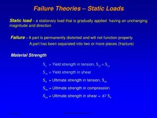
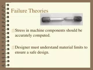
Theories of Failure Failure of a member is defined as one of two conditions. 1. Fracture of the material of which the member is made. This type of failure is the characteristic of brittle materials. 2. Initiation of inelastic (Plastic) behavior in the material. This type of failure is the one generally exhibited by ductile materials. When an engineer is faced with the problem of design using a specific material, it becomes important to place an upper limit on the state of stress that defines the material's failure. If the material is ductile, failure is usually specified by the initiation of yielding, whereas if the material is brittle it isspecified by fracture.
These modes of failure are readily defined if the member is subjected to a uniaxial state of stress, as in the case of simple tension however, if the member is subjected to biaxial or triaxial stress, the criteria for failure becomes more difficult to establish. Inthis section we will discuss four theories that are often used in engineering practice to predict the failure of a material subjected to a multiaxial state of stress. A failure theory is a criterion that is used in an effort to predict the failure of a given material when subjected to a complex stress condition.
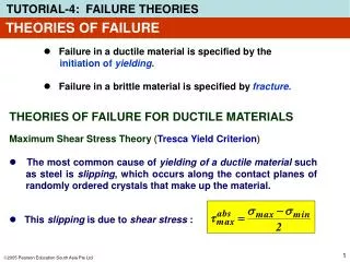
Several theories are available however, only four important theories are discussed here. • Maximum shear stress (Tresca) theory for ductile materials. • Maximum principal stress (Rankine) theory. • Maximum normal strain (Saint Venan’s) theory. • Maximum shear strain (Distortion Energy) theory.
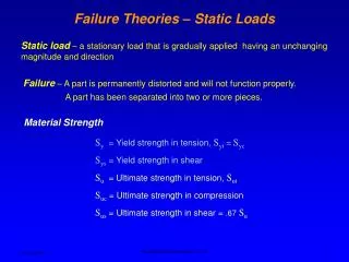
Maximum shear stress theory for Ductile Materials The French engineer Tresca proposed this theory. It states that a member subjected to any state of stress fails (yields) when the maximum shearing stress (τmax)in the member becomes equal to the yield point stress (τy)in a simple tension or compression test (Uniaxial test). Since the maximum shear stress in a material under uniaxial stress condition is one half the value of normal stress and the maximum normal stress (maximum principal stress) is max, then from Mohr’s circle.
In case of Biaxial stress state If both of principal stresses are of the same sign tension compression then σ1 <σy (4) σ2 <σy (5)
A graph of these equation is given in the figure. Any given state of stress will be represented in this figure by a point of co-ordinate 1 and 2 where 1 and 2 are two principal stresses. If these point falls within the area shown, the member is safe and if outside then member fails as a result of yielding of material. The Hexagon associated with the initiation of yield in the member is known as “Tresca Hexagon”. (1814-1885). In the first and third quadrant 1 and 2 have the same signs and
max is half of the numerically larger value of principal stress 1 or 2. In the second and fourth quad, where 1 and 2 are of opposite sign, max is half of arithmetical sum of the two 1 and 2. In fourth quadrant, the equation of the boundary or limit (yield/boundary stress) stress line is 1 - 2 = y And in the second quadrant the relation is 1 - 2 = -y
Problem 01:- The solid circular shaft in Fig. (a) is subject to belt pulls at each end and is simply supported at the two bearings. The material has a yield point of 36,000 Ib/in2• Determine the required diameter of the shaft using the maximum shear stress theory together with a safety factor of 3.
400 + 200 lb 200 + 500 lb
Problem 02 The state of plane stress shown occurs at a critical point of a steel machine component. As a result of several tensile tests, it has been found that the tensile yield strength is y= 250 MPa for the grade of steel used. Determine the factor of safety with respect to yield, using (a) the maximum-shearing-stress criterion, and (b) the maximum-distortion-energy criterion.
SOLUTION Mohr's Circle. We construct Mohr's circle for the given state of stress and find Principal Stresses a. Maximum-Shearing-Stress Criterion. Since for the grade of steel used the tensile strength is ay = 250 MPa, the corresponding shearing stress at yield is
b. Maximum-Distortion-Energy Criterion. Introducing a factor of safety into Eq. (7.26), we write For a= +85 MPa, b= -45 MPa, and y= 250 MPa, we have
Comment. For a ductile material with y= 250 MPa, we have drawn the hexagon associated with the maximum-shearing-stress criterion and the ellipse associated with the maximum-distortion-energy criterion. The given state of plane stress is represented by point H of coordinates a= 85 MPa and b= -45 MPa. We note that the straight line drawn through points O and H intersects the hexagon at point T and the ellipse at point M. For each criterion, the value obtained for F.S. can be verified by measuring the line segments indicated and computing their ratios:
Example 10-12 The solid shaft shown in Fig. 10-41a has a radius of 0.5 in. and is made of steel having a yield stress of y= 36 ksi. Determine if the loadings cause the shaft to fail according to the maximum-shear-stress theory and the maximum-distortion-energy theory. Solution The state of stress in the shaft is caused by both the axial force and the torque. Since maximum shear stress caused by the torque occurs in the material at the outer surface, we have
The stress components are shown acting on an element of material at point A in Fig. 10-41b.Rather than using Mohr's circle, the principal stresses can also be obtained using the stress-transformation equations, Eq.9-5.
= -9.55 ± 19.11 CTI = 9.56 ksi CT2 = -28.66 ksi Maximum-Shear-Stress Theory.Since the principal stresses have opposite signs, then from Sec. 9.5, the absolute maximum shear stress will occur in the plane, and therefore, applying the second of Eq. 10-27, we have
Thus, shear failure of the material will occur according to this theory. Maximum-Distortion-Energy Theory. Applying Eq. 10-30, we have Using this theory, failure will not occur.
Maximum Principal Stress theory or (Rankine Theory) According to this theory, it is assumed that when a member is subjected to any state of stress, fails (fracture of brittle material or yielding of ductile material) when the principal stress of largest magnitude. (1) in the member reaches to a limiting value that is equal to the ultimate normal stress, the material can sustain when subjected to simple tension or compression. The equations are shown graphically as
These equations are shown graphically if the point obtained by plotting the values of 1 + 2 falls within the square area the member is safe.
It can be seen that stress co-ordinate 1 and 2 at a point in the material falls on the boundary for outside the shaded area, the material is said to be fractured failed. Experimentally, it has been found to be in close agreement with the behavior of brittle material that have stress-strain diagram similar in both tension and compression. It cab be further noticed that in first and third quad, the boundary is the save as for maximum shear stress theory. Problem A thin-walled cylindrical pressure vessel is subject to an internal pressure of 600 lb/in2. the mean radius of the cylinder is 15in. If the material ha a yield point of 39,000lb/in2 and a safety of 3 is employed,
determine the required wall thickness using (a) the maximum normal stress theory, and (b) the Huber-von Mises-Hencky theory. P = 600psi. r = 15" y = 39000psi F.O.S = 3 t = ? According to Circumferential stress / girth stress
By comparing 1 = c. Thus, According to the normal stress theory, maximum Principal stress should be equal to yield stress/FOS i.e. |1| ≤ ult |2| ≤ ult f = maximum (|1|, |2|, |3| - ult = 0)
As y = 39000psi Problem 02:- The solid circular shaft in Fig. 18-12(a) is subject to belt pulls at each end and is simply supported at the two bearings. The material has a yield point of 36,000 Ib/in2• Determine the required diameter of the shaft using the maximum normal stress theory together with a safety factor of 3.
400 + 200 lb 200 + 500 lb
Mohr’s Criterion:- In some material such as cast iron, have much greater strength in compression than tension so Mohr proposed that is 1st and third quadrant of a failure brokes, a maximum principal stress theory was appropriate based on the ultimate strength of materials in tension or compression. Therefore in 2nd and 4th quad, where the maximum shear stress theory should apply. Pure shear is one in which x and y are equal but of opposite sense.
Failure or strength envelope Pure shear Smaller tension strength Largest compressive strength
tension compression
Problem 3:- In a cast-iron component the maximum principal stress is to be limited to one-third of the tensile strength . Determine the maximum value of the minimum principal stresses ,using the Mohr theory. What would be the values of the principal stresses "associated with a maximum shear stress of 390 MN/m2? The tensile and compressive strengths of the cast iron are 360 MN/m2 and 1.41 GN/m2 respectively
By using principal stress theory Maximum principal stress = 360/3 = 120 MN/m2 (tension). According to Mohr's theory, in the second and fourth quadrant From (a) and (b)
Therefore The Mohr's stress circle construction for the second part of this problem is shown in Fig. 13.7. If the maximum shear stress is 390 MN/m2, a circle is drawn of radius 390 units to touch the two envelope lines. The principal stresses can then be read off as +200 MN/m2 and -580 MN/m2•
Example 10-11 The solid cast-iron shaft shown in Fig. 10-40ais subjected to a torque of T = 400 Ib . ft. Determine its smallest radius so that it does not fail according to the maximum-normal-stress theory. A specimen of cast iron, tested in tension, has an ultimate stress of (σult)t = 20 ksi. Solution The maximum or critical stress occurs at a point located on the surface of the shaft. Assuming the shaft to have a radius r, the shear stress is