Download
1 / 25
4.37k likes | 15.83k Views
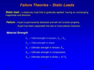
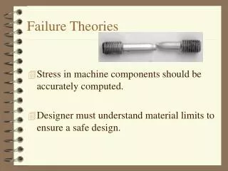
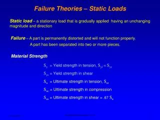
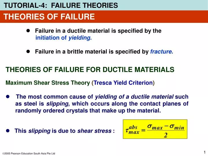
THEORIES OF FAILURE. Failure in a ductile material is specified by the initiation of yielding. Failure in a brittle material is specified by fracture. THEORIES OF FAILURE FOR DUCTILE MATERIALS. Maximum Shear Stress Theory ( Tresca Yield Criterion ).

E N D
THEORIES OF FAILURE • Failure in a ductile material is specified by the initiation of yielding. • Failure in a brittle material is specified by fracture. THEORIES OF FAILURE FOR DUCTILE MATERIALS Maximum Shear Stress Theory (Tresca Yield Criterion) • The most common cause of yielding of a ductile materialsuch as steel is slipping, which occurs along the contact planes of randomly ordered crystals that make up the material. • This slipping is due to shear stress :
s1 and s2 have same sign s1 and s2 have opposite sign THEORIES OF FAILURE The maximum shear stress theory for plane stress can be expressed for any two in-plane principal stresses as s1 and s2 by the following criteria:
s3 s1 s2 s2 s1 THEORIES OF FAILURE Maximum Distortion Energy Theory (von Mises Yield Criterion) von Mises Stress for 3-Dimension von Mises Stress for 2-Dimension so = sy Yield stress,sy, occurs when
where THEORIES OF FAILURE Allowable Stress, sallow & Safety Factor, SF In designing a component or structure, it is introduced what so-called Allowable Stress, which is defined as
45o Failure of a brittle material in torsion Failure of a brittle material in tension THEORIES OF FAILURE THEORIES OF FAILURE FOR BRITTLE MATERIALS If the material is subjected to plane stress, we require that
(a) (a) (b) PROBLEM-1 Stress in Shafts Due to Axial Load and Torsion An axial force of 900 N and a torque of 2.50 N.m are applied to the shaft as shown in the figure. If the shaft has a diameter of 40 mm and the safety factor is 5, determine the minimum yield stress of the material used. Internal Loadings The internal loadings consist of the torque and the axial load is shown in Fig.(b)
(a) (b) 198.9 kPa PROBLEM-1 Maximum stress Components • Due to axial load • Due to torsional load
= – 29o PROBLEM-1 The state of stress at point P is defined by these two stress components Principal Stresses: We get s1 = 767.8 kPa s2 = – 51.6 kPa The orientation of the principal plane:
PROBLEM-1 von Misesequivalent stress for 2-D = 794.8 kPa Yield Stress of the shaft material can be found from: = (5)(794.8) kPa = 3974 kPa = 3.974 MPa
PROBLEM-2 Solid shaft has a radius of 0.5 cm and made of steel having yield stress of Y = 360 MPa. Determine if the loadings cause the shaft to fail according to the maximum-shear-stress theory and the maximum-distortion-energy theory.
PROBLEM-2 State of stress in shaft caused by axial force and torque. Since maximum shear stress caused by torque occurs in material at outer surface, we have
PROBLEM-2 Stress components acting on an element of material at pt A. Rather than use Mohr’s circle, principal stresses are obtained using stress-transformation eqns 9-5:
PROBLEM-2 Maximum-shear-stress theory Since principal stresses have opposite signs, absolute maximum shear stress occur in the plane, apply Eqn 10-27, Thus, shear failure occurs by maximum-shear-stress theory.
T y x z PROBLEM-3 Stress in Shaft due to Bending Load and Torsion A shaft has a diameter of 4 cm. The cutting section shows in the figure is subjected to a bending moment of2 kNm and a torque of 2.5 kNm. • Determine: • The critical point of the section • The stress state of the critical point. • The principal stresses and its orientation. • Select the material if SF = 6
T A y x z PROBLEM-3 Analysis to identify the critical point • Due to the torque T Maximum shear stresses occur at the peripheral of the section. • Due to the bending moment M Maximum tensile stress occurs at the bottom point (A) of the section. Conclusion: the bottom point (A) is the critical point
T A y x z PROBLEM-3 Stress components • Due to the torque T 198.9 kPa • Due to the bending moment M 318.3 kPa
198.9 kPa 318.3 kPa s2 s1 25.65o PROBLEM-3 Stress state at critical point A txy = 198.9 kPa sx = 318.3 kPa Principal stresses We get s1 = 413.9 kPa s2 = – 95.6 kPa The orientation of the principal plane: = 51.33o
s2 s1 25.65o PROBLEM-3 von Misesequivalent stress for 2-D = 469 kPa Yield Stress of the shaft material can be found from: = (6)(469) kPa = 2814 kPa = 2.814MPa
PROBLEM-4 Steel pipe has inner diameter of 60 mm and outer diameter of 80 mm. If it is subjected to a torsional moment of 8 kN·m and a bending moment of 3.5 kN·m, determine if these loadings cause failure as defined by the maximum-distortion-energy theory. Yield stress for the steel found from a tension test is Y = 250 MPa.
PROBLEM-4 Investigate a pt on pipe that is subjected to a state of maximum critical stress. Torsional and bending moments are uniform throughout the pipe’s length. At arbitrary section a-a, loadings produce the stress distributions shown.
PROBLEM-4 By inspection, pts A and B subjected to same state of critical stress. Stress at A,
PROBLEM-4 Mohr’s circle for this state of stress has center located at The radius is calculated from the shaded triangle to be R = 127.1 and the in-plane principal stresses are
PROBLEM-4 Using Eqn 10-30, we have Since criterion is met, material within the pipe will not yield (“fail”) according to the maximum-distortion-energy theory.
PROBLEM-5 Stress in Shafts Due to Axial Load, Bending and Torsion A shaft has a diameter of 4 cm. The cutting section shows in the figure is subjected to a compressive force of 2500 N, a bending moment of800 Nm and a torque of 1500 Nm. Determine: 1. The stress state of point A. 2. The principal stresses and its orientation 3. Determine the required yield stress if SF = 4.
t s PROBLEM-5 Analysis of the stress components at point A • Due to comprsv load: • Due to torsional load: • Due to bending load: (compressive stress) Stress state at point A Shear stress: t = tA Normal stress: s = sA’ + sA”