Download
1 / 26
260 likes | 464 Views
Magnet, Support and Infrastructure. Robin Wines July 9, 2014. Engineering Progress Efforts in cost and labor estimate Contributions to pCDR document Visit to Cornell. Dry Run - Magnet - Hall A Layout for SoLID - Magnet Modifications - Magnet Support - Detector Supports

E N D
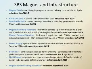
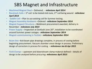
Magnet, Support and Infrastructure Robin Wines July 9, 2014
Engineering Progress • Efforts in cost and labor estimate • Contributions to pCDR document • Visit to Cornell • Dry Run • - Magnet • - Hall A Layout for SoLID • - Magnet Modifications • - Magnet Support • - Detector Supports • - Power and Utilities • -Transport and Storage of CLEO II • - Cost and Labor Estimates • Preliminary material, needs to be refined, much more than 20 minutes
SoLID EM Calorimeter (forward angle) EM Calorimeter (forward angle) Cherenkov EM Calorimeter (large angle) MRPC Baffle Collmator Target GEM Target GEM Light Gas Cherenkov Heavy Gas Cherenkov CLEO II Coil and Yoke PVDIS SIDIS
Magnet • CLEO II magnet to be used for the SoLID spectrometer • Solenoid magnet with a uniform axial central field of 1.5 T • Large inner space with a clear bore diameter of 2.9 m • Coil diameter of 3.1 m , coil length of 3.5 m • Built in 1989, operated until 2008 • Met with Cornell engineers in June 2014 to discuss design, operation and transport of magnet to Jlab. Details in available trip reports. • Items available from Cornell: Superconducting magnet, Octagonal iron shielding, Magnet transport frame/cradle, Dynapower DC power supply, Valve control box, Cryogenic bayonets, Data acquisition, Rotation/turning jigs, Steel mounting blocks, Third iron layer (on top pf the magnet) + yellow plate to support the 700 liter dewar, Transfer lines, Readout boxes for strain gauge • Projected disassembly in Summer 2015 and transport from Cornell in Summer 2016 • New information : Recommendation to replace vapor cooled current leads due to significant heat load – discuss with Cryo Group.
Hall A Floor Loading 500 ton • SoLID magnet and detectors encompass an • area of 5.8 meters in diameter and 7.3 meters long. • Clearance to the Hall floor ranges from 10 to 38 cm, sufficient for support. • Weight of the CLEO-II magnet, detector hut and detectors is 1300 tons. The floor in this installation region is designed for 250 tons for a 12 square foot pad. SoLID footprint 500 ton 28’ 250 ton 82’ 58’
CLEO II in Hall A • The experiment layout puts the HRS arms at 90 degrees to the beamline on the left and right. Alternate layout places both HRS arms to the left of beamline. • Target to be 115cm downstream of pivot for magnet to clear pivot bearing. Center of the CLEO-II magnet would be 350 cm downstream of the target center.
Magnet Modifications NEW PARTS MODIFIED PARTS Endcap donut Barrel Yoke Outer Endcap bottom Barrel Yoke Inner Endcap nose Collar downstream Front Piece Shield Endcap Donut Barrel Yoke Outer Endcap Bottom Collar Downstream Spacer Spacer Barrel Yoke Inner Collar Upstream Coil Front Piece shield Endcap Nose
Magnet Modifications • The CLEO magnet will require some modifications to its design for use in the SoLID experiments. • SoLID will not use the outermost muon ring. It will use the inner two rings, each consisting of 8 slabs of iron. Each of these slabs will have to be shortened to allow the proper position of the endcap. • The original upstream coil collar will be reused. • The downstream coil collar will be modified if an economical way of reducing its thickness can be found without wasting a majority of its unwanted material. If a solution is not found then a new downstream coil collar will be created. • Additional pieces of iron will need to be fabricated to allow for the proper mating of the endcap with the barrel yoke. • . All supporting structure for the magnet barrel yoke and detector endcap will be new fabrications. • The endcap, which consists of the outer cylindrical ring, the backplate, and endcap nose, will all be made from new material.
The endcap will be split vertically into halves and be capable of separation to allow for access to the detector package. • The endcap nose with a secondary backing plate will be a cast two piece design to allow for separation. • Each section of the nose will bolt to the main backplate which consists of a two piece round disk. • The two halves of the cylindrical outer ring will bolt to the corresponding backplate.
Magnet Support • The initial plan used for estimating the cost is to build a stationary frame and distribute the approximate 1000 ton load of the modified CLEO-II magnet section using eight 200 ton enerpac jacks. • Steel plates and large steel blocks and/or large I-beams will be used to distribute the load out over a safe area. • The 200 ton jacks will be used for vertical alignment and have locking rings which allow for a full mechanical connection and not rely on hydraulic pressure for stationary support.
Endcap Support • The endcap will have a support structure that cradles each half the cylindrical ring. • The structure will be integrated into a track system that is mounted to steel plates resting upon the concrete floor. • The initial design concept for the track system requires a set of longitudinal (downstream direction) tracks for moving the endcap away from the magnet. A second set of tracks that would separate the endcap halves in the lateral direction would ride on top of the longitudinal tracks. • The endcap support structure would then be attached to the top lateral track system. • Motion can be achieved by using hydraulic or electric cylinders to push and pull the entire system into position
Detector Supports • The magnet will be located adjacent to the existing Hall A center pivot/target mount area and will have limited access to the front of the magnet. • The insertion of the large angle detector packages that will reside internal to the cryostat will be accomplished from the downstream side of the magnet using a supporting framework to roll the packages in and out. This will require the detector hut to be moved downstream to allow access to the cryostat. • An internal frame system is needed to mount the lead baffles in the PVDIS experiment. The frame cannot come into contact with the inside bore of the cryostat. This requires the frame to span the entire length of the cryostat and mount to the return yoke iron. • The rails of the frame will be fabricated from 4 inch diameter schedule 80 welded stainless steel pipe. Either 304 or 316 grade stainless is acceptable. • The downstream end of the rails will have a hemispherical cap and a stainless steel foot welded on and will be bolted to the downstream collar. The upstream end of the rail will either be bolted or welded to an annular stainless steel plate. • The upstream end of the frame will be mounted to the frontcup • Since the frontcup has to be movable to balance the magnetic field on the coils the annular plate will be attached to the frontcup with studs. This will allow the rail framework to remain stationary if the frontcup has to be adjusted. The same rail system can be used for the SIDIS experiment for mounting the large angle calorimeter and GEM’s
Large Angle Detector and Baffle Installation • An installation mechanism is needed to load the large angle detector packages and baffle system into the internal support structure • This mechanism will likely be mounted to the longitudinal track system used for the endcap movement and can utilize the tracks for rolling the detectors and baffles into the cryostat and transferring the load to the internal frame.
Light Gas Cherenkov Installation • The light gas Cherenkov will mount to the external downstream end of the magnet and will not traverse with endcap. When the endcap is in the operational position the light gas Cherenkov will be enclosed within the cylindrical ring along with the rest of the forward angle detectors. • The light gas Cherenkov detector will be made up of six pie shaped sections that will need to be bolted to the downstream side of the magnet. • A space frame similar to a scaffolding system would hold and position each section while being attached to magnet. The space frame would attach to the rail system and could be movable along the rails if needed. The space frame will be suitable for personnel access to allow workers to perform the installation and maintenance of the detectors
Endcap Forward Angle Detector Installation • The basic design concept for the detectors mounted inside the endcap will have them supported by individual rails mounted to the inner circumference of the cylindrical ring and on rails attached to the outer horizontal circumferential surface of the nose if needed. • The heavy gas Cherenkov will be separated into six sections with each section utilizing two rails to attach the section to the outer circumference of the endcap. • A counterweight balanced installation device that is slung from the crane can be used to orient and position each section onto the rails. • Personnel access to the endcap will be through man lifts and/or a specialized scaffolding as needed
Power Requirements • The projected electrical power load is 1.6MVA, maximum current for magnet at 3266A. The present power consumption for Hall A is less than 1 MVA. So upgrade to the Hall substation to have 2 MVA is required • The CLEO-II magnet is designed to have a low cryogenic heat load with passive cooling. The HRS arms will not be operational during SoLID, so it is expected that the refrigeration heat load will be less than needed for HRS.
Transport and Storage of CLEO II • Disassembled and loaded on trucks for shipping by the Cornell personnel with oversight by Jefferson Lab. It will require 52 trucks to transport the magnet and related equipment. • We have identified all of the parts of the CLEO magnet, with sizes and weights, anticipating a need for storage of these parts at Jefferson Lab starting Summer 2016, total weight of 1,053k lbs. • The cryostat (35k lbs) and power supply will need to be stored in an environment-controlled area of approximately 400 square feet. Jefferson Lab projects the use of the CMSA site for storage of all parts.
Cost and Labor for Magnet K$ and FTE
Cost and Labor for Detector Supports and Hall Infrastructure
Analysis Additional slides
New downstream coil collar • Allowable stress for 1008 hot rolled steel = 14820 psi • Peak stress due to rigid constraint at the bottom is the only overstress. Conservative simple restraint. • Buckling not checked – will be retained by the slabs. • Forces due to gravity only
Detector hut stress analysis Half of detector weight placed on the outer shell and half on the nose Forces due to gravity only Only overstress is from rigid constraint • Light gas Cherenkov = 6 metric t • Heavy gas Cherenkov = 8 metric t (assumed) • Calorimeter = 23 metric t • W forward angle absorber = 13 metric t Inside Outside