Download
1 / 21
210 likes | 386 Views
Non-Contact Ranging Sensors. Robert Blaser Assignment #1 Mechatronics—ECE 5320. Outline. Reference List To Explore Further… Major Applications Introduction Ranging Techniques Employed Non-Contact Range Sensor Basics Laser-Based TOF Systems SICK LMS 200. Reference List.

E N D
Non-Contact Ranging Sensors Robert Blaser Assignment #1 Mechatronics—ECE 5320
Outline • Reference List • To Explore Further… • Major Applications • Introduction • Ranging Techniques Employed • Non-Contact Range Sensor Basics • Laser-Based TOF Systems • SICK LMS 200
Reference List • Robert H. Bishop, THE MECHATRONICS HANDBOOK, CRC Press, 2002. • Robosoft, (2004, Feb. 29). “Laser Measurement System (LMS)” (2003) [Online]. Available: http://www.robosoft.fr/SHEET/02Local/1004SickLMS200/SickLMS200.html • SICK, (2004, Mar. 1). “SICK Products” (2004) [Online]. Available: http://www.sick.de/de/products/categories/auto/lasermeasurementsystemsindoor/lms200indoor/en.html
To Explore Further… • Large variety of range sensors useful with mobile robots • http://www.andrew.cmu.edu/~rjg/websensors/robot_sensors2.html#range • Resource sites explaining how different types of range sensors work • http://www.cs.brown.edu/people/tld/courses/cs148/02/sonar.html • http://abrobotics.tripod.com/Snuffy/GP2D12.htm
Major Applications • Measurement of objects • Determination of object volumes • Determination of object ranges • Classification of objects • Monitoring storage capacity • Positioning • Determining the position of objects • Navigational support • Monitoring areas • Collision prevention • Counting people
Introduction • Non-Contact Range sensors use a number of technologies including light/optics, microwave, and ultrasonic to measure the distance from a reference point to an object. • Non-Contact Range sensors all measure distances to an object with no physical contact, as the name implies.
Ranging Techniques Employed • Time of Flight (pulsed) • Triangulation • Phase-shift Measurement • Frequency Modulation • Interferometry • Swept Focus • Return Signal Intensity
Non-Contact Range Sensor Basics... • Classification • Active • Sensor radiates some form of energy into the field of interest. Some typical sensors in this category include radar, sonar and lidar. • Passive • Sensor relies on energy emitted from objects or targets of interest.
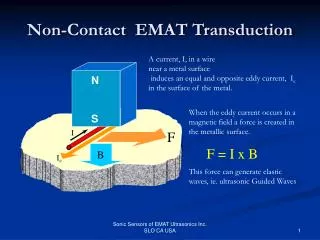
Non-Contact Range Sensor Basics… Time Of Flight (TOF) Technique • The figure below shows a conceptual diagram with the Emitter and Receiver both located at the sensor. • The distance, d, in the diagram is defined as: where c is the speed of light and TOF is the time of flight measured in seconds. This equation changes a little when using sub- speed of light ranging sensors. “The Mechatronics Handbook”
Non-Contact Range Sensor Basics… • There are two basic methods for defining the Time Of Flight (TOF) • Beginning of signal burst to end of returning burst • Beginning of signal burst to maximum amplitude of returning burst (higher accuracies possible) “The Mechatronics Handbook” “The Mechatronics Handbook”
Non-Contact Range Sensor Basics… • Potential sources of error for TOF systems • Variations in the speed of propagation (Large factor in acoustical systems) • Uncertainties in determining the exact time of arrival of a returning pulse • Inaccuracies in the timing circuitry used to measure the round-trip TOF • Interaction of the incident wave with the target surface
Non-Contact Range Sensor Basics… • Variations in speed of popagation: • Propagation speed variations for electromagnetic energy are small and can be omitted for most applications except satellite-based systems and similar. However, when using acoustic systems propagation variations exist and need to be accounted for. Temperature changes, humidity and air content all influence the speed of sound enough to require proper adjustments.
Non-Contact Range Sensor Basics… • Detection Uncertainties: • Detection time errors can occur because of two main reasons. The first is varying reflectivity of surfaces and the second is signal attenuation due to distance. Different target surfaces lead to a reflected pulse with varying degrees in amplitude for different targets at the same distance. Signal attenuation must also be accounted for due to spherical divergence.
Non-Contact Range Sensor Basics… • Inaccuracies in the timing circuitry: • When using electromagnetic energy the timing circuitry has to be very precise due to the shorter wavelengths and fast propagation speeds. In fact, sub-nanosecond circuitry is required to even attain resolutions down to a foot. To attain resolutions down to 1mm requires circuitry with an accuracy of 3ps. This type of timing circuitry is expensive. Therefore without very expensive circuitry systems based on electromagnetic energy tend to show inaccuracies.
Non-Contact Range Sensor Basics… • Target surface interactions: • When light, sound and radio waves strike a target surface they get scattered in different directions. The type of surface determines the amount of scattering. Some of these scattered waves can reflect off other objects also and essentially add ‘noise’ to the system. Angles of incidence are also important as reflected waves can not even make it back to the receiver if it hits the target above a critical angle. All of these factors make it harder to process the returned signal.
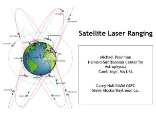
Laser-Based TOF Systems • First appeared in the 1970s at the Jet Propulsion Laboratory, Pasadena CA. • Extremely short laser pulses are emitted rapidly pointed directly at the target. • Uses TOF measurements to find range • Accurate resolutions available but at increased costs.
SICK LMS 200 • The LMS 200 is a non-contact Laser Measurement System that scans its surroundings two-dimensionally like laser radar. It operates within a temperature range of between 0 °C and +50 °C and, as an active scanning system, requires no auxiliary passive components such as reflectors or position markers. The LMS 200‘s high resolution allows it to take on tasks that were hitherto impossible or could only be achieved with difficulty or at great cost. “SICK Products” LMS 200 Operating Principle “Laser Measurement System (LMS)”
SICK LMS 200 • SICK LMS 200 Specifications: “SICK Products” “SICK Products”
SICK LMS 200 • Typical sample application of SICK LMS 200 Minimizing the time and costs of luggage logistics is a top priority for airport management. With the help of the Laser Measurement System LMS 200 it is possible to classify luggage automatically during its transportation. In this way it can be recognized very soon, if a piece of luggage fits into a conveyor container of known dimensions. Standstill times and the costs of personnel will be reduced. “SICK Products”
SICK LMS 200 • Other applications of SICK LMS 200 There are many applications that the SICK LMS 200 can be used for. The pictures below show just a few varying applications. “SICK Products”
SICK LMS 200 • Advantages of SICK LMS 200 • Very accurate • Great for many applications • Reliable • Disadvantages of SICK LMS 200 • Physically larger than other range sensors • More expensive than other range sensors • Complex design