Download
1 / 15
150 likes | 227 Views
Modeling and Integration of Peripheral Devices. purpose. Search : automation methods for device driver development in IP-based embedded systems in order to achieve high reliability, productivity, reusability and fast time to market. Section 2 : reviews related work

E N D
purpose • Search : automation methods for device driver development in IP-based embedded systems in order to achieve high reliability, productivity, reusability and fast time to market. • Section 2 : reviews related work • Section 3 : describes the framework for our methodology • Section 4 presents the formal specification of device behavior using the Universal Serial Bus (USB) as an example • Section 5 discusses driver synthesis • Section 6 case study • Section 7 discusses future work and directions.
Introduction • Device drivers • It provide a bridge between a peripheral device and the upper layers of the operating system and the application software • It significantly affect design quality and productivity • Necessary knowledge • chips and boards, processors, peripherals, operating systems, compilers, logic and timing requirements • important • Ex) Motorola MPC860 PowerQUIC-board support package (BSP) • 25000 lines of C code – complexity • Ex) Microsoft Windows XP crash data • that 61% of XP crashes are caused by driver problems - reliability
Methodology Framework 2 Methodology Framework Driver Environment Framework Overview
3 Methodology Framework • Core functions • Trace the states of devices, enforce device state transitions required for certain operations, and operate data paths. • Platform functions • glue the core functions to the hardware and OS platform • virtual environment : architectural behaviors - big or little endian, programmed I/O, memory mapped I/O. It also specifies OS services and OS requirements - memory management, DMA/bus controllers, synchronization mechanisms etc. • Registry functions • To export driver services into the kernel or application name space. • Ex) The interface can register a driver class to the NT I/O manager (IOM) or fill one entry of the VFS (Virtual File Switching) structure of the Unix kernel
3 Methodology Framework • device specification • provides all the information about the device required by the driver core function synthesis process(Core Gen). Core functions are implemented in the virtual environment • mapper • maps core functions in the virtual environment to the target environment. • The driver configuration defines the target platform and necessary parameters.-OS name, processor name, bus name, device instance parameters SA1100 USB Device Controller (UDC) Driver Configuration
4 Device Specification • Device specification • input to the generation of the core functions • Partition Part • Data Path • It defined as a stream of data units. • data unit data block moving between the device and the software by a primitive hardware operation. • Device Control • It specifies the state changes of a device. • device may be composed of several sub-devices operating in parallel, we use a concurrency model, event driven finite state machines • 4type of event : hardware events, input events, output events and internal events. • Device Programming Interface specification
4 Device Specification • Control Function Specification • Control functions are responsible for changing the control state of the device according to the state machines. • Device Programming Interface specification • To model device register accesses, we use the concepts of register and variable
5.Synthesis • the synthesis process synthesizes the C code for the entire driver • synthesis process. • Platform Function and Registry Function Mapping • This part is done manually based on the platform • All virtual data types and API are mapped into platform specific types and API. • Synchronization functions • Timer management functions • Memory management functions • DMA and bus access functions • Interrupt handling (setup, enable, disable, etc.) • Tracing functions • Register/memory access functions.
5.Synthesis • Linux 2.4 Mapping of the Primitive Specified /*synchronization object */ Data Type: iblk_unit Operations: IDECLARE_BLK_UNIT(name) /* block on bu */ inline void iblk(iblk_unit bu); /* unblock */ inline void iunblock(iblk_unit bu); /*check if any one is blocked on bu*/ inline int ichk_blk(iblk_unit bu); typedef wait_queue_head_t iblk_unit; #define IDECLARE_BLK_UNIT(name) \ DECLARE_WAIT_QUEUE_HEAD(name) inline void iblk(iblk_unit *bu) { sleep_on(bu); } inline void iunblock(iblk_unit *bu) { wake_up (bu); } inline int ichk_blk(iblk_unit *bu) { return(waitqueue_active(bu)); }
5.Synthesis • DeviceCore Function Synthesis • device driver core functions : data access functions or control functions • data access functions <- data path specification • control functions <- device control specification. • Synchronization Mechanisms • Data Access Function • Synchronous communication • It achieved by synchronizing the caller and the callbackfunction • Callback - notify the completion of a data transfer • data path - modeled as a stream of data units
5.Synthesis • Control Function - it moves the device to a particular state. The execution of application software depends on such a state change • control function involves a series of • state transitions. • It completes when the final state set • is reached. void ctrl(DEV_PRIV_DS *priv, IEsmEvtVal val) { Enqueue the input event; while (true) { while(firable transitions exist){ Fire the transition; if(final state set is reached) return; } block(time_out_value); } } Fig. Control Function
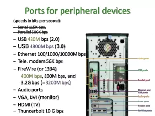
6 Case Study • Condition : Intel StrongArm SA1100 • peripheral control module contains a universal serial bus (USB) endpoint controller • supports three endpoints: • endpoint 0 (ep0): USB host controls the UDC • endpoint 1 (ep1): transmit FIFO • endpoint 2 (ep2):receive FIFO. • Ethernet device driver interface has been implemented on top of the USB data flow.
6 Case Study • Modeling • UDC and synthesized a UDC Linux device driver:Ethernet driver interface and manages data transfer and USB connection setup • UDC ep1 : OUT data path • UDC ep2 : IN data path • UDC control : 4 state machines: one state machine for each endpoint and one state machine managing the USB protocol state of the device
7 Conclusions and future work • Issues : addresses the complexity and portability • A platform independent specification is used to synthesize platform independent driver code, which is then mapped to a specific platform using platform specific library functions • expectation : This methodology greatly simplifies driver development as it makes it possible for developers to provide this specification and then leverage the synthesis procedures as well as the library code reuse to derive significant productivity benefits