Download
1 / 135
1.38k likes | 1.6k Views
Chapter 10. Input/Output Interface Circuits and LSI Peripheral Devices. Chapter nine covers the following topics:. 10.1 Core and Special-Purpose I/O Interfaces 10.2 Byte-Wide Output Ports Using Isolated I/O 10.3 Byte-Wide Input Ports Using Isolated I/O

E N D
Chapter 10 Input/Output Interface Circuits and LSI Peripheral Devices
Chapter nine covers the following topics: 10.1 Core and Special-Purpose I/O Interfaces 10.2 Byte-Wide Output Ports Using Isolated I/O 10.3 Byte-Wide Input Ports Using Isolated I/O 10.4 Input/Output Handshaking and a Parallel Printer Interface 10.5 82C55A Programmable Peripheral Interface 10.6 82C55A Implementation of Parallel Input/Output Ports 10.7 Memory-Mapped Input/Output Ports 10.8 82C54 Programmable Interval Timer 10.9 82C37A Programmable Direct Memory Access Controller 10.10 Serial Communications Interface 10.11 Programmable Communication Interface Controllers 10.12 Keyboard and Display Interface 10.13 8279 Programmable Keyboard/Display Controller
10.1 CORE AND SPECIAL-PURPOSE I/O INTERFACES Special-Purpose I/O Interfaces Keyboard, Display, Parallel Printer Interface, LAN Interface, They are referred to as special-purpose interfaces because not all microcomputer systems employ each of these types. They are all implemented in the original PC as add-on cards Core Input/Output Interfaces Parallel input/output ports, interval timers, and direct memory access control Interfaces that are also considered to be part of the I/O subsystem. These I/O functions are employed by most microcomputer systems
IO.2 BYTE-WIDE OUTPUT PORTS USING ISOLATED I/O address of port 0 is 10000000000000002= 800016 However, if these bits are all made equal to 1 instead of 0, the address is 11111111111100002 =FFF016 other examples are 8FF016 and F00016 Check examples 10.1 & 10.2
Time-Delay Loop and Blinking an LED at an output port Sequence of instructions needed to initialize0 7 to logic 0. MOV DX, 8000H ;Initialize address of port 0 MOV AL, 00H ;Load data with bit 7 as logic 0 ON_OFF: OUT DX, AL ;Output the data to port 0 delay for a short period of time so as to maintain the data written to the LED MOV CX, 0FFFFH ;Load delay count of FFFFH HERE: LOOP HERE ;Time delay loop the value in bit 7 of AL is complemented to 1 and then a jump is performed to return to the output operation that writes the data to the output port: XOR AL, 80H ;Complement bit 7 of AL JMP ON_OFF ;Repeat to output the new bit 7
Polling technique In practical applications, it is sometimes necessary within an I/O service routine to repeatedly read the value at an input line and test this value for a specific logic level. Let us assume that we want to read the contents of port 0, and that input I3 at this port is the line that is being polled.
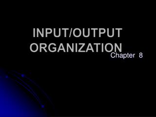
10.4 INPUT/OUTPUT HANDSHAKING AND A PARALLEL PRINTER INTERFACE In some applications, the microcomputer must synchronize the input or output of information to a peripheral device. Two examples of interfaces that may require a synchronized data transfer are a serial communications interface and a parallel printer interface. Sometimes it is necessary as part of the I/O synchronization process first to poll an input from an I/O device and, after receiving the appropriate level at the poll input, to acknowledge this fact to the device with an output. This type of synchronization is achieved by implementing what is known as handshaking as part of the input/output interface.
conceptual view of the interface between the printer and a parallel printer port. There are three general types of signals at the printer interface: data, control, and status.
Setting Busy check Data out Strobe pulse Update Repeat
10.5 82C554 PROGRAMMABLE PERIPHERAL INTERFACE The 82C55A is an LSI peripheral designed to permit easy implementation of parallel I/O in the 8088- and 8086-microcomputer systems. It provides a flexible parallel interface, which includes features such as single-bit, 4-bit, and byte-wide input and output ports: level-sensitive inputs; latched outputs; strobed inputs or outputs; and strobed bidirectional input/outputs. These features are selected under software control.
Operation Modes of 82C55 Mode 0 selects what is called simple I/O operation where the lines of the port can be configured as level-sensitive inputs or latched outputs. Mode 1 operation represents what is known as strobed I/O. In this way, the A and B ports are configured as two independent byte-wide I/O ports, each of which has a 4-bit control/data port associated with it. The control/data ports are formed from the lower and upper nibbles of port C, respectively. Mode 2, represents what is known as strobed bidirectional I/O. The key difference is that now the port works as either inputs or outputs and control signals are provided for both functions. Only port A can be configured to work in this way.
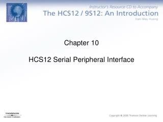
Mode 1 (strobed I/O) In this way, the A and B ports are configured as two independent byte-wide I/O ports, each of which has a 4-bit control/data port associated with it. The control/data ports are formed from the lower and upper nibbles of port C, respectively.
Mode 1 (strobed I/O) When configured in this way, data applied to an input port must be strobed in with a signal produced in external hardware. An output port in mode 1 is provided with handshake signals that indicate when new data are available at its outputs and when an external device has read these values. Strobe input (STBA) Interrupt request (INTRA) Input buffer full (IBFA) Interrupt enable (INTEA) Acknowledge (ACKA) Output buffer full (OBFA)
Mode 2 (strobed bidirectional I/O) The key difference is that now the port works as either inputs or outputs and control signals are provided for both functions. Only port A can be configured to work in this way.
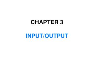
Status information for port C The MPU can be programmed to read the control information from port C through software. This is known as reading the status of port C. The format of the status information input by reading port C of an 82C55A operating in mode 1 The format of the status information input by reading port C of an 82C55A operating in mode 2
By using a software handshake sequence that tests the status bits to change the program sequence, hardware signals such as interrupts can be saved. For instance, if port A is used as an input in mode 1, the processor can read (poll) the status register and check bit D3 for INTRA. If D3 is 1, INTRA is active and the processor is signaled to read the data from port A of the 82C55A. In this way, the INTRA output may not be connected to the processor and one interrupt request input is saved.