Download
1 / 50
600 likes | 891 Views
Welcome you to the training. The INDUCTION HOB. ANALOGY WITH THE TRANSFORMER. DeschaJ: Stacking up of iron strip = empilement de lames de metal. THE SKIN EFFECT Principle. In a wire. In the pan. Resulting current. Bottom of the pan. Density of current. Thickness of the pan. Gas.

E N D
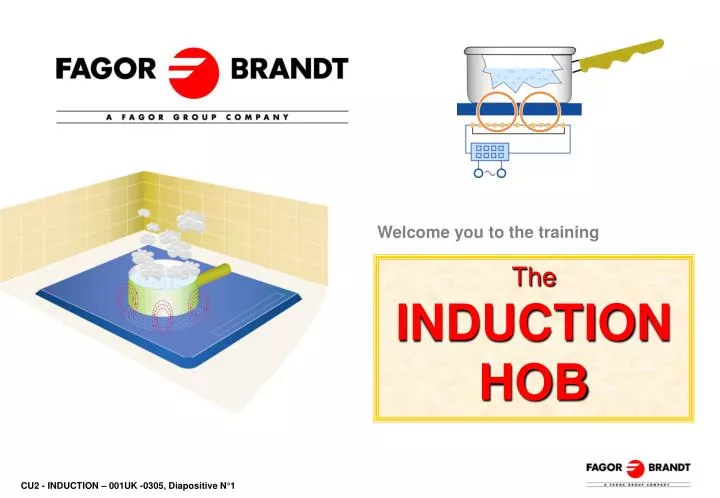
Welcome you to the training TheINDUCTION HOB
ANALOGY WITH THE TRANSFORMER DeschaJ: Stacking up of iron strip = empilement de lames de metal
THE SKIN EFFECT Principle In a wire In the pan Resulting current Bottom of the pan Density of current Thickness of the pan
Gas Cast iron Radiant Halogen Induction 10 20 30 40 50 60 70 80 90% EFFICIENCY comparative rate It results significant energy savings
QUICKNESS OF HEAT RADIANTHALOGEN GAS CAST IRON INDUCTION Time required to bring 2 litres of water from 20°C to 95°C
QUICKNESS OF COOLING RADIANTHALOGEN GAS CAST IRON INDUCTION Decreasing to 60°C after boiling 2 litres of water
THE PANS If you choose a pan with this logo, you will be certain that it is absolutely compatible with your induction hob under normal condition of use • The compatible induction pans must be made of a magnetic material : • Enamelled steel pans with or without non-stick coating • In cast iron with or without enamel coating • In ferrous stainless steel – laminated stainless steel • In aluminium with special bottom We advise to choose pans with a thick bottom and a minimum diameter of 12 cm (i.e. 5 inches) for even more cooking : the heat spreads more evenly
Diameter announced by the pan manufacturer Bottom diameter THE PANS 190mm 160mm « Crown effect» Pan Inductor 160mm & 180mm Middle crown : 2800W maxi External crown : 1800W maxi Inductor 280mm "Krone"
FITTING Fixing supplied with the hob SEAL
FITTING ABOVE A UNIT WITH A DOOR OR A DRAWER 1- In case of a small cross piece, there is no problem 2- In case of a rectangular cross piece or with a closed top, make a bevelled cut so that air comes out of the hob 3- In case of an intensive using with more than 1 cooking zone, we advise to make an opening on both sides of the unit
FITTING ABOVE AN OVEN Oven in lower position Oven in upper position Other brand of oven Same brand of oven
FITTING ABOVE A DISHWASHER The top of the dishwasher must be covered with an insulation plate (77X7781). Ensure that there is a minimum opening of cool air.
Fitting with current range With our ovens With other ovens
ELECTRICAL CONNECTIONS 230 V single live Connect the 3 cables on your installation, observing the correct cable colours 400 V 2N three lives Connect the 4 cables on your installation, observing the correct cable colours
USINGSetting 9, 12 or 15 levels of power from 50 to 2800W A ‘Booster’option function enables the cooking zone to reach 3600W
USING Continuum zone 4600W
USING Allow to memorize a complete cycle of cooking (maximum 5 different power/time) "STARTCONTROL" End of cooking programmed (maximum power 6) HU (HEAT UP)
USINGSafety Automatic-Stop Children safety residual heat display Conformity with electromagnetic disturbance standards Clean lock
IX1 1991 IX2 1992-1995 IX7 09/2007 Evolution of induction hobs
SYNOPTIC OF A GENERATOR Main power Filter 5 and 12V= power Command level Rectifier keyboard Inverter 19 to 50Khz Pilot of inverter Inductors
THE KEYBOARDSwith capacitive keys High frequency signal
THE CURRENT FILTER • Protections against over-current due to the work of the hob • Stop the outside and inside interferences • Stop the outside over current
THE FILTER IX3 and IX3WR Earth screw Fuse tracks Direct live Live wire Neutral via the relay Neutral Direct neutral Command Relay 15V= Supply of the fan Power relay
THE RECTIFIER Filter rectifier After rectifier Before rectifier Filter rectifier • Bialternation rectifier by diode bridge • Filtering of high frequencies by condenser Outside current 310 V= when hob doesn’t work
THE TRANSISTOR INVERTER V/2 Inductor Rectified current V V/2 • 2 power transistors • 2 condenser • 2 diodes
Step 1 THE INVERTERWorking Step3 Step2 Step4
Standard THE INDUCTORS 160mm 180mm 210mm « Krône » inductor Triple crown 280mm 230mm
GENERATOR TRIPLE CROWN INDUCTOR or • 3 coils • Pan diameter from 12 to 26 cm • Only fitted on IX3WR and IX6 • Power from 50 to 2800W • ‘Booster’ 3200W
GENERATOR « KRÔNE » INDUCTOR • 2 coils • Pan diameter from 12 to 32 cm • fitted on IX3, IX3WR IX4000 and IX6 • Power from 50 to 2800W • ‘Booster’ 3600W
Tangential fan Filter card with « fast » fuse Power card Command card To keyboard IX1 GENERATION • Share-out among 2 relays • 4 PCB • Manufactured from 1990 to 1992
Fan Filter card + power and command card To keyboard IX2 GENERATION • Repartition by 2 relay • 2 cards • Manufactured from 1992 to 1996
230V~ GENERATION IX3 Earth screw, required when hob is working • Repartition by 2 relay • 3 cards • Manufactured since 1996 Supply of the fan Relay of répartition Bipolar transistors Rear CTN Front CTN diode bridge Plug in keyboard
IX3 Possible configurations
230V~ IX3WR GENERATION Filter card Earth screw, required when hob is working • Share-out through transistors • 3 cards • 3 crown cooking zones • Manufactured since 2000 Supply of the fan 3 crowns cooking zone relay supplying Transistors Diodes bridge Rear CTN Front CTN Transistors Plug in keyboard
IX4000 GENERATION • Share-out with 1 relay • 2 cards • Start of manufacturing 09/2002 • Replaced gradually IX3
IX6 GENERATION • Share-out with 1 relay and a twin transistors inverters • 2 cards • Start of manufacturing 04/2005 • Replaced gradually IX3WR
IX7 GENERATION 2 cooking zone 3 cooking zone
IX7 GENERATION 3 cooking zone with continuum zone 4 cooking zone
IX7 GENERATION Fan connector Fan Rectifier IGBT transistors µP Keyboard connector Inductorconnectors NTC connectors
IX7 GENERATION Inductors/NTC connecting chart
DIAGNOSTICBreakdown of the vitroceramic glass Impact Contraction Overheating of the cooking zone (radiant or halogen) Tightening too important
Good Bad Copper wirevisibleInsulationmissing DIAGNOSTIC No pan detection or random reset Bad smell during the first use Noise vibration coming from the inductor Ferrite unglued
DIAGNOSTIC ‘Error’ Messages IX3 HOB Other ranges of hobs *
DIAGNOSTICIX3, IX3WR, IX4000, IX4006, IX6 2 A.S.S. keyboards • IX3 with 6 wire cables • Other ranges with 8 wire cables • IX3 ASS KEYBOARD : 79X5460 • Connector : 79X5461 • OTHER RANGES ASS KEYBOARD : 79X9920 • Connector : 79X9921