Download
1 / 46
460 likes | 592 Views
UK R&D Infrastructures and Accelerator Programmes. Jim Clarke STFC Daresbury Laboratory TIARA-PP F inal M eeting Daresbury Laboratory 25 th November 2013. Outline. National Accelerator Facilities Diamond Light Source ISIS Neutron Source Test Accelerators FETS MICE ALICE EMMA

E N D
UK R&D Infrastructures and Accelerator Programmes Jim Clarke STFC DaresburyLaboratory TIARA-PP Final Meeting Daresbury Laboratory 25th November 2013
Outline • National Accelerator Facilities • Diamond Light Source • ISIS Neutron Source • Test Accelerators • FETS • MICE • ALICE • EMMA • VELA • CLARA • ALPHA-X • Summary
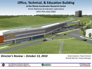
Diamond Light Source 3 GeVelectron storage ring generating bright, stable, light enabling high quality research across a broad research base: • Chemistry • Cultural Heritage • Earth Science • Engineering • Environmental Science • Life Sciences • Physics and Material Science Diamond Light Source at Rutherford Appleton Laboratory http://www.diamond.ac.uk/
Low-coupling mode: Micro-focusing 44m 3.7m • Vertical coupling reduced from 1% to 0.3% during operations • Low coupling smaller source smaller focused beam DCM µ-focus • E=15 keV B16-BM CRL • Compound Refractive Lenses CRLS – 18 lenses • Photon Energy ~15 keV • Source demagnification: 3.7m / 44m (~1/12) • Knife edge scans using 200 µm Au wire • Focused beam size at sample reduced by 35%
Low-coupling mode: Nano-focusing 47m 73mm DCM • Low coupling smaller source smaller focused beam n-focus • E=8 keV B16-BM FZP • Fresnel Zone Plate – Z150/75/1W5 • (150 µm diameter, 75 nm outer zone width) • Source demagnification: 73 mm / 47m (~1/644) • Knife edge scans using 200 µm Au wire • Nano-focused beam (v) also reduced (from 144 nm to 124 nm)
Brilliance upgrade at Diamond Brilliance improvement for Diamond reduced coupling 1% 0.3% 300 mA 500 mA reducing diamond emittance with present hardware 2.7 nm 2.1 nm lattice test – ongoing: issues with SCWs Initial studies for an ultra low emittance lattice for Diamond-II 5BA 7BA, and modified 4BA Thanks to T. Pulampong, R. Walker, J. Kay and N. Hammond Riccardo Bartolini
upgrade with Diamond-II (200pm): 300mA and 1%K Assuming the operation with a 200pm lattice Brilliance plot using U27 – 72 periods 2 m long with Kmax = 2.02 10 mm gap Tuning curves computed with Spectra 8.0 Riccardo Bartolini
doubling the number of beamlineswhile still pushing the emittance down Modified 4BA - 320 pm 4BA with an additional short straight section between the dipole pairsemittance not pushed as for a pure 4BA but can double the number of straight sectionsLength of additional straight sections forced to be at least 3 m while keeping the remaining 6.7 m and 9 m straight sections Riccardo Bartolini
Modified 4BA cell Broken the 4 BA cell to leave 3 m space 12 quads per cell 10 Sextupoles per cell Straight section length slightly reduced 11 m 9.7 m 8.3 m 6.7 m Riccardo Bartolini
Modfied 4BA – one superperiod Ring circumference shrinks from 561.6 to 561.0 -> loss 1 harmonic of RF Gradient in bend < 15 T/m Quads gradient < 70 T/m Riccardo Bartolini
ISIS ISIS at Rutherford Appleton Laboratory Spallation neutron source based upon an 800 MeV proton synchrotron, enabling high quality science: • Physics • Chemistry • Materials Science • Earth Science • Engineering • Biology http://www.isis.stfc.ac.uk/ John Thomason
New 180 MeV Linac ISIS Injection Upgrade 70 MeV Linac • A New 180 MeV Injector • Update old linac • Increase beam power ~0.5 MW • Advantages • Reduces Space Charge (factor 2.6) • Chopped, Optimised Injection & Trapping • Challenges • Injection straight • Activation (180 MeV) • Space charge, beam stability, .... MICE 800 MeV Synchrotron TS1 TS2 John Thomason
ISIS Injection Upgrade Ring Physics Study • Snapshots of the work: challenges of getting 0.5 MW in the ISIS Ring Injection Longitudinal Dynamics Injection Straight Modelling Injection Straight Analytical Work Simulation Results Evolution of bunch Test Distribution Foil temperatures Injected distributions in (x,x’),(y,y’),(,dE) RF Bucket Variation of key parameters Transverse & Full Cycle 3D Dynamics Other Essentials: Activation, Diagnostics Predicted Space Charge Limit Activation vs Energy Activation Measurements Single particle tune shift distributions at 0.5 MW Coherent Tune Shift and Resonance Electron Cloud Monitor Strip-line Monitor/Kicker Accelerated distributions in (x,x’),(y,y’),(,dE) John Thomason
John Thomason Ring High Intensity Beam Studies on ISIS • Some of our R&D Studies • Half-integer intensity limit in proton rings • Using the ISIS ring to study halo formation • New simulation code: Set 3Di • Model losses, benchmark on ISIS Simulation Simulation Measurement Y profile (Y,Y) Y profile • Head-tail instability • Key for high intensity proton rings • Higher order loss effects and images • Investigating complex loss mechanisms Vertical difference signal (along bunch, many turns) Vertical dipole motion along bunch on successive turns Image driven resonance Loss vs Q measurement Samples along bunch Turn
Front End Test Stand (FETS) • FETS at Rutherford Appleton Laboratory aims to demonstrate key technologies for the front end of the next generation of high power pulsed proton accelerators. http://fets.isis.rl.ac.uk/ John Thomason
Front End Test Stand (FETS) John Thomason • High brightness H– ion source • 4 kW peak-power arc discharge • 60 mA, 0.25πmm mrad beam • 2 ms, 50 Hz pulsed operation • Radio Frequency Quadrupole • Four-vane, 324 MHz, 3 MeV • 4 metre bolted construction • High power efficiency • Diagnostics • Non-interceptive • Well distributed • Laser-based • Low Energy Beam Transport • Three-solenoid configuration • Space-charge neutralisation • 5600 litre/s total pumping speed • Medium Energy Beam Transport • Re-buncher cavities and EM quads • Novel ‘fast-slow’ perfect chopping • Low emittance growth
John Thomason FETS Ion Source R&D • FETS applications include: • ISIS upgrades • Future Spallation Neutron Sources • Neutrino Factory • Waste Transmutation • ADSR • FETS uses the ISIS Penning type ion source and is already delivering world class performance. • The FETS specification is for a 60 mA beam in 2 ms pulses at 50 Hz. εH = 0.38 πmm.mrad (norm rms) εV = 0.37 πmm.mrad (norm rms)
FETS Low Energy Beam Transport • FETS uses a 3 solenoid magnetic LEBT to match the beam from the ion source into the RFQ. Horizontal emittance 0.4 πmm.mRadrms norm Vertical emittance 0.3 πmm.mRadrms norm John Thomason
Ion Source, LEBT and RFQ • New high power, high duty factor ion source extraction power supply • Low energy beam transport section alignment improved • Beam centred, symmetric in phase space and matched into RFQ • First metre section of Radio Frequency Quadrupole is at RAL • Remaining three metres in final machining stage • Cavity, vacuum and RF testing from Winter 2013 to Summer 2014 • First RFQ beam anticipated late 2014 John Thomason
Muon Ionisation Cooling Experiment (MICE) • Slow down muons in a light absorber, then re-accelerate in beam direction using RF cavities. • All of which are immersed in a magnetic channel to confine the muon beam. • MICE on ISIS will commission and operate a realistic section of cooling channel. • Measure its performance in a variety of modes of operation and beam conditions. • Results will allow future Neutrino Factory complex to be optimised. http://mice.iit.edu/ John Thomason
MICE Hardware Development Tracker Focus Coil Absorber Cavity Module 200 MHz Cavity RF Be Window Coupling Coil John Thomason
RF power specification achieved at Daresbury Forward power into load Amplifier system has been dismantled from Daresbury and is currently being installed in the MICE hall
Accelerators and Lasers In Combined Experiments (ALICE) • ALICE at Daresbury Laboratory operates using the Energy Recovery principle. • Used as an R&D test facility for next generation electron beam technology development. Compressor Photoinjector Laser 8 MeV IR-FEL Booster 35 MeV 8 MeV Peter McIntosh http://www.stfc.ac.uk/ASTeC/Programmes/17425.aspx
Peter McIntosh New ALICE Cryomodule • International collaboration initiated in early 2006: • ASTeC (STFC) • Cornell University • DESY • FZD-Rossendorf • LBNL • Stanford University • TRIUMF • Fabricate optimised ERL cryomodule and validate with beam. • Dimensioned to fit on ALICE: • Same CM footprint • Same cryo/RF interconnects • ‘Plug Compatible’
Cryomodule Evolution Cavity Absorber Tuner Integration Peter McIntosh
Cryomodule Reality Absorber Cavity Integration Tuner Peter McIntosh
Cryomodule Status • Installed into ALICE in early 2013 • RF & beam commissioning delayed by cryoplant problems – unrelated to cryomodule! • RF Conditioning started 14th Nov • Both cavities have exceeded 10 MV/m, no surprises so far, field emission low • So far, so good
ALICE THz Exploitation • CSR generated in THz Region as bunch length ~1 ps. • Output enhanced by many orders of magnitude. • Dedicated tissue culture laboratory. • Effect of THz on living cells being studied. • Source has very high peak intensities but very low average power: • no thermal effects! Tissue Culture Facility IR/THz from ALICE Peter McIntosh/Peter Weightman
Peter McIntosh/Peter Weightman FEL Exploitation Cancerous Tissue • Oesophageal cancer is the fastest rising cancer in the western world. • Surgery is the only curative treatment but survival rates are poor because of late diagnosis. • Challenge is to identify patients with oesophageal cancer much earlier. Detection Signature: • Cancer cells surrounded by stroma made up of various (non-cancer) cell types and ExtraCellular Matrix (ECM) proteins. • Increase in number and change of morphology and architecture, relates to the function of the cancerous DNA molecules. • Scanning Near Field Optical Microscope (SNOM) is ideal probe • Resolution: • Synchrotron (diffraction limited) 3 μm • ALICE Free Electron Laser (FEL) 0.1 μm • Key is intensity and stability of the IR source. Non-Cancerous Tissue ALICE will now be dedicated to cancer studies for 4 months per year
Electron Model for Many Applications (EMMA) • Uses ALICE as its injector • World’s first and only Non-Scaling FFAG accelerator. • EMMA is an electron beam demonstrator: • Verification of NS-FFAG beam dynamics. • First acceleration demonstrated in 2011 • Possible applications: • Muonbeam acceleration • High intensity proton source for ADSR energy production • Flexible source for proton and carbon therapy http://www.conform.ac.uk/ Peter McIntosh
VELA (Versatile Electron Linear Accelerator) • High brightness RF Photoinjector at Daresbury • Essential technology for advanced electron facilities • Light sources • Colliders • First RF Photoinjector in the UK • New tool for industry to develop new accelerator-based technologies • Healthcare • Security scanners • Water treatment • …. • Two independent beam areas available • Funded August 2011 • First Beam April 2013 Gun cavity and klystron provided by Strathclyde University/ALPHA-X
VELA Exploitation First Industrial Users on VELA (Sep 2013): • RapiscanSystems (UK) and UCL spent 2 weeks exploiting VELA’s ultra-short pulse properties to demonstrate a new time-of-flight imaging technique. • This 3-year collaborative programme with STFC will potentially enable the next generation of cargo screening equipment. Academic Users are also encouraged: • JAI will test new cavity BPMs in 2014 • York/Swansea/UCL will carry out first electron diffraction commissioning in 2014 • CI/Strathclyde proposing plasma acceleration experiments (new laser room with existing TW laser should be available Feb 2014) • Test of DLS 1 kHz RF photoinjector in 2014 • New flexible end station for rapid turnaround of experiments being designed now (enabling tests of dielectric structures, manipulation of phase space by THz, photonic structures, …)
CLARA (Compact Linear Accelerator for Research and Applications) • Free Electron Lasers • Ultra high peak intensity • Very short pulses of light • Tuneable • Basic FEL unstable in intensity and wavelength • Immature as a technology, plenty of scope for improvement • Fortunately lots of ideas exist for improving FEL stability (wavelength and intensity) and to make even shorter pulses of light but very few have been tested
The CLARA Concept There are many ways FELs can be improved, but limited scope with existing facilities UK Scientists need FELs and we want to develop next generation FEL technology towards a possible UK facility CLARACompact Linear Accelerator for Research and Applications An upgrade of the existing VELA Photoinjector Facility at Daresbury Laboratory to a Free-Electron Laser Test Facility Proof-of-principle demonstrations of novel FEL concepts Emphasis is ULTRA-SHORT PULSE GENERATION Neil Thompson
CLARA Schematic FEL OUTPUT STUDIED FEL OUTPUT GENERATED The existing VELA RF Photoinjector Facility INTERACTIONS WITH LASER BEAMS ELECTRONS ACCELERATED AND MANIPULATED ELECTRONS GENERATED HERE Neil Thompson
Example Schemes Here are two recent novel ideas, proposed by ASTeCand Strathclyde, which could be demonstrated in proof-of-principle experiments on CLARA Mode-Locked AfterburnerA compact extension to an existing free-electron laser, which in the X-ray would produce Gigawatt pulses of only 700 zeptosecond duration, leapfrogging current demonstrated techniques by orders of magnitude High-Brightness SASEA way of ‘slowing down’ the electron bunch in the free-electron laser to generate single wavelength X-ray pulses, without the need for a laser seed or any optics Neil Thompson
Other Goals and Benefits of CLARA • The development of advanced technologies: • New photoinjector technologies • Novel undulators(short period, cryogenic, superconducting….) • New accelerating structures • Single bunch diagnostics. • The enhancement of VELA beam power and repetition rate, enabling additional industrial applications. • The possibility to use the electron beam for other scientific research applications: COMPTON SCATTERING FOR GAMMA BEAMS PLASMA ACCELERATOR RESEARCH ULTRAFAST ELECTRON DIFFRACTION DIELECTRIC WAKEFIELD ACCELERATION NONEQUILIBRIUM STORAGE RINGS Neil Thompson
ALPHA-X Mark Wiggins
Summary • The UK operates two national accelerator facilities, Diamond and ISIS • Both have excellent performance and a vibrant user base • Both have major upgrade plans under development • The UK has a number of test accelerators covering a broad remit • High power proton applications • Muon cooling demonstration • Light source/FEL motivated (based upon energy recovery, NC Linac, & LPWA) • Industrial applications