Download
1 / 31
310 likes | 493 Views
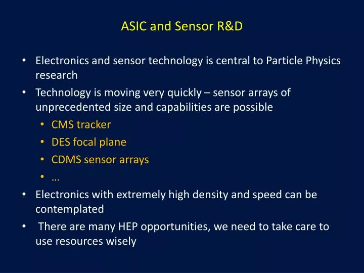
ASIC and Sensor R&D. Electronics and sensor technology is central to Particle Physics research Technology is moving very quickly – sensor arrays of unprecedented size and capabilities are possible CMS tracker DES focal plane CDMS sensor arrays …

E N D
ASIC and Sensor R&D • Electronics and sensor technology is central to Particle Physics research • Technology is moving very quickly – sensor arrays of unprecedented size and capabilities are possible • CMS tracker • DES focal plane • CDMS sensor arrays • … • Electronics with extremely high density and speed can be contemplated • There are many HEP opportunities, we need to take care to use resources wisely
ASIC/Sensor Projects and Technologies We have focused on a few technologies which can have significant impact on HEP • Lepton Collider Vertex • X-Ray Imaging • CMS Track Trigger • LHC fast tracker • Digital SIPM Projects Technologies 3D Electronics Silicon-on-insulator Device processing(with partners)
Future Challenges • Lepton Collider Vertex Detector - precision • Superb impact parameter resolution ( 5µm 10µm/(p sin3/2) ) • Transparency ( ~0.1% X0 per layer ) • Muon Collider – processing to deal with harsh background environments • 1-3 TeVmuon collider on FNAL site • Substantial Huge detector and radiation backgrounds • Fast timing for background rejection • CLIC – speed and precision • Few ns time resolution • SLHC – large scale, high speed, harsh environment • 200-400 int/25 ns crossing, track trigger required • Large scale systems • On-detector background rejection • X-Ray Imaging – speed and density • Variety of challenges – timing • Intensity frontier • Thin, fast electronics Building a toolboxto deal with these challenges
ILC Vertex • Much of this work started withILC vertex R&D • ILC vertex detectors present a particularly difficult challenge • < 5 micron resolution -> small pixels • Mass/layer <10% of LHC detectors -> air cooling, low power • Time stamping • Then available technologies (CCD, CMOS pixel… ) could not cope • Fermilab began to study 3D integration as a way of integrating complex functionality in a small pixel
IBM/Cornell/UCSB Study – vision of 22 nm 10Tflop 3D chip (2018) 3D • 2 or more layers of active semiconductor devices that have been thinned, bonded and interconnected to form a “monolithic” circuit. • Industry is moving toward 3D to improve circuit performance. • Reduce R, L, C for higher speed • Reduce chip I/O pads • Provide increased functionality • Reduce interconnect power and crosstalk Provides a set of technologies to thin, bond and interconnect heterogeneous circuits and sensors into a monolithic assembly
3D Interconnects Cu-Cu Adhesive (Tezzaron) Oxide (RTI) (Ziptronix) Cu-Sn Indium (T-Micro) (IZM)
3D For ILC Our initial 3D work was in collaborationwith MIT-LL, aimed at a small pixel for International Linear Collider Oxide bonded tiers of 0.18 mm SOI • 20 micron pitch pixel, 3 tiers • Time stamping and sparse readout • 64 x 64 pixels • First iteration had a number of processing issues • Learned a lot about dealing with a leading edge R&D process • Second iteration with more conservative design works well
VIP2a Results Second iteration test chip open Disc. reset, take 1st sample open Int. reset Inject input Discriminator fires Take 2nd sample Digital out (for Inject = 50 mV) Inject = 50 mV Inject = 100 mV Integrator out Inject = 200 mV Differential analog out : (Before out) – (After out) Mux high (read out)
Commercial 3D Recently we have partnered with Tezzaron Inc. (Naperville Ill) to organize the first commercial 3D multiproject run for HEP. • Based on Tezzaron Cu-Cu bonding • 0.13 micron CMOS from Chartered/Global Foundries • 6 micron imbedded TSVs • Face-to-face bonding
Multiproject Run Contributions from 17 institutions • Separate PMOS and NMOS for MAPS • LHC Pixel • ILC Pixel • X-ray imaging • LHC track triggering
Commercialization • MOSIS/CMP/CMC (silicon brokers in US, France, and Canada) • Agreement with Tezzaron for commercialization • June 2010 - Announced plan to offer 3D services using Tezzaron • Working with Fermilab to make HEP 3D efforts available to the commercial world • Design platform is being developed by KholdounTorki at CMP and the first version is now available • MOSIS, CMP, and CMC will all receive designs • MOSIS will assemble designs into a reticule • Tezzaron will handle the final processing of the 3D frame (e.g. adding bond pad interface fill, etc.) and submit design to Chartered.
Sensor Integration • 3D technologies can also be used to integrate sensors to ICs • Pitches as small as 3 microns, thinned to 25 microns • Provides for fully active sensors as large as 6” (or 8” wafer) based on tiled ROICs • We have also developed a thinning and laser-based annealing process for low leakage sensors as thin as 50 m FPIX Chip on FNAL/MIT-LL Sensor
FPIX/Sensor Tests • BTeV FPIX bonded to MIT-LL sensor • Thinned to 100 m • Noise studies • Laser, x-ray, beam tests • Good, low cap. bond
SOI R&D • Silicon on insulator devices with high resistivity detector handle wafers - OKI and American Semiconductor (ASI) • Truly integrated sensor/electronics • Last run demonstrated integration of SOI electronics with high resistivity substrate on 8” wafers Minimal interconnects, low node capacitance not to scale High resistivity Silicon wafer, Thinned to 50- 100 microns Backside implanted and laser annealed after processing
Backgate effects • The potential of the substrate can change the fields at the top transistor and affect performance – “backgate” • Backgateeffects significant in OKI process and limit bias that can be applied • Digital-analog coupling can also destroy performance • FNAL suggested process changes to OKI to fix this • Initial tests show the chips are not significantly affected by back potential This well separates digital circuits from sensor substrate and preventsback gating effects This well collects the charge Patent application underdiscussion
SOI Devices • MAMBO II pixel layout MAMBO x-ray imaging counting pixel chip • Maximum counting rate ~ 1 MHz • Each pixel: CSA, CR-RC2 shaper, discriminator + 12 bit binary counter 47mm 13 diodes in parallel connection
CMS Track Trigger • At SLHC standard trigger menu saturates • Track-based triggering needed to explore new physics We are designing a level 1 track trigger for CMS II • >150 m2 of silicon, >900 M channels • 40 Mhz crossings, 200 interactions/crossing, • 2.75x1013 bits/second of hit data in the tracker • Process this information to make a decision on whether an event is “interesting” • Can only record ~1/400 • Need to make a decision on the event within 3.2 ms
Filter out data from low momentum tracks-reduce data by >20 • Curvature information in 4T field can be analyzed locally an a 3D chip – minimal data transfer and associated power • Stacked layers ~ 1mm apart • Local processing and local hit correlation • Exploring the concept for muon collider as well
Track Trigger Projects • Large area arrays (see later) • Small demonstrator module • Interposer • VICTR Chip • Sensors • Full Module • Interposer development • High speed, fault tolerant, data flow design • Mechanical supports • Simulation Short Strip Tier Long Strip Tier
Fast Trigger/Tracker • Content Addressable Memory stack (CAM) can simultaneously compare external patterns to stored templates. • Very fast pattern recognition – at the cost of silicon area • CAMs were used in the CDF SVT • Similar concept being developed for ATLAS FTK • FNAL is working on custom ASIC design
Fast Tracker • 3D concept can also be used to correlate hits in a multilayer CAM stack • Extending the CAM concept to 3D improves density, speed, and power consumption
Large Area Arrays • The CMS track trigger requires 10x10 cm modules with ~25 chips/module • Bonding yield may be ~ 95% • Overall yield (.95)25 ~ 0 • Use active edge silicon detector to use known good sensor/detector die – use high yield bump bonds to connect to PCB • Saw cut edges on normal silicon are sources of leakage current – stay 3x depth away to limit leakage current - creates dead areas • Ion etching used in 3D processes can produce an “atomically smooth” edge – small leakage and sensitive to within a few microns of the edge
cut 10m ROIC TSV wafer 2m DBI DBI sensor sensor etch 200m ROIC DBI 1m SOI bond SOI bond sensor handle 500m Active edge
Digital SIPMs • Geiger mode avalanche photodiodes (SIPMs) are an emerging replacement for the phototube • They are inherently digital – but read out as analog sum of hit pixels • Access to digital information using 3D through-silicon-vias would allow • Active quenching – faster, less after-pulsing • Digital hit counting • Position resolution • Pixel masking • Precise timing • Good QE
Digital SIPM Development • Establish bonding technology (underway) • Work with SIPM fabricator to obtain full wafers • Use vias inserted post fabrication (via last) or pre fabrication (via first) • Design electronics • Build and test TSV
R&D Collaborations (a partial list) • Industry • Tezzaron • Ziptronix • OKI • American Semiconductor • Vega Wave • Laboratories • SLAC • BNL • LBL • CERN • MIT-LL • KEK • Sandia - beginning • Universities • Cornell (laser anneal, large area arrays, simulation, testing) • Brown • Northwestern • UC Davis • North Carolina • + 17 in 3D collaboration
I read these guidelines from Erik after I prepared the talk • A short overview of the various ASIC and sensor projects • Not so short • How these projects will extend into the future. Do you foresee problems with resources? • ILC work morphing into other things – other projects have clear paths • Physicist and testing resources are scarce for all projects • What are the best avenues for new silicon R&D to pursue. Do you need new facilities? • There are many opportunities – the hard part is matching our stomachs to our eyes. For us 3D is the enabling common thread. • Modern test hardware and design software is crucial and needs continuing investment • Technology, once developed, needs to be applied – a difficult problem with decades between experiments • How does this tie in with the national picture? Are we falling behind, or breaking new ground? • We are real leaders in this field, but we need to collaborate with commercial firms, universities, and other labs that all have unique capabilities
Frontiers Precision frontier Processing Frontier Scale Frontier This is obviously a shameless attempt to co-opt the Quantum Universe – and doesn’t really work – but we are all friends