Download
1 / 8
90 likes | 247 Views
Typical Digital Modulation Methods M-PSK DPSK M-QAM (Linear amplifiers required “AM”) FSK OQPSK/MSK – I and Q phase transitions are offset in time so that 180 o phase shifts are never encountered. Q. Q. X. X. X. I. I. X. X. X. X. X. OQPSK – Offset Square Pulses.

E N D
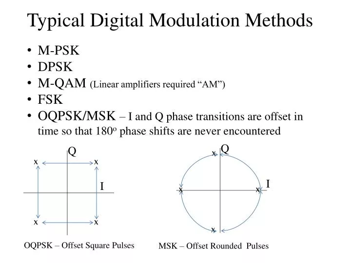
Typical Digital Modulation Methods • M-PSK • DPSK • M-QAM (Linear amplifiers required “AM”) • FSK • OQPSK/MSK – I and Q phase transitions are offset in time so that 180o phase shifts are never encountered Q Q X X X I I X X X X X OQPSK – Offset Square Pulses MSK – Offset Rounded Pulses
Data p/4-DQPSK Encoder Q X Memory X 10 X 00 I 1 of 8 Phase Select X X X X 01 11 X X X X Delay X
Pulse Spectra Contributes to Adjacent Channel ISI Rounding the pulses makes the spectrum more square and reduces ISI potential.
Low pass filtering of the data pulses improves spectral behavior Raised Cosine Trapezoidal 1.0 1.0 D D 0.5 0.5 D D fN BT BT fN fb/2 NRZ fN = fb RZ fbAMI
Discussion: Nyquist chose to use filters with these special characteristics because they yielded to tractable mathematical analysis and provided practical and useful results. However , trapezoidal and raised cosine filter characteristics cannot be realized with discrete components, but can be very closely approximated with non-real-time digital filters . By incorporating a time delay, the filter can operate on previous as well as “future” data pulses to realize the desired characteristics.
CDMA IS-95 PCS Vo-Coder 8-13 kb/sec PCM Voice Signal Convolutional Encoding Block Interleaving Modulation: QPSK Uplink OQPSK Downlink Walsh Code Spreading 1.23 Mchips/sec Tx 800 Mhz Cell site demodulates and reconstructs digital uplink stream, then re-modulates for downlink. Each user has unique orthogonal Walsh code
Modulator/Demodulator Performance I Data: I(kT) g (leakage) Splitter Unbalance Error b Carrier Oscillator cos(wot) S S(t) -p/2 -fe g (leakage) Q Data: Q(kT)
Ideal Demodulator LPF Recovered I Data: IR(kT) Carrier Recovery cos(wot) S(t) Splitter Splitter -(p/2) Recovered Q Data: QR(kT) LPF