Download
1 / 17

E N D
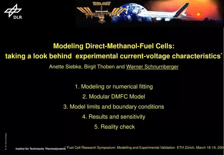
Modeling Direct-Methanol-Fuel Cells:taking a look behind experimental current-voltage characteristics*Anette Siebke, Birgit Thoben and Werner Schnurnberger1. Modeling or numerical fitting 2. Modular DMFC Model 3. Model limits and boundary conditions 4. Results and sensitivity 5. Reality check* Fuel Cell Research Symposium: Modelling and Experimental Validation ETH Zürich, March 18-19, 2004
Oxygen 95 0C 50 0C Air 95 0C 50 0C V = E - Vact - Vohm - Vconc V = E - [ V0 + Va(1-e-c1i)] - [iRohm] - [i(c2 i/imax)c3] V (T; pi,; i;)
SOFC Variation of Oxygen partial pressure (single cell test)
PEFC in situ analytical tools: Electrochemical Impedance Spectra (EIS) O E=1024 mV; i= 0 mA/cm2 E= 841 mV; i= 45 mA/cm2 E= 597 mV; i= 392 mA/cm2 + E= 317 mV; i= 761 mA/cm2 EIS: Bode diagramm PEFC ( E-TEK Electrodes, Nafion 117), at 80°C, pH2=pO2=1bar, at different current densities / cell voltages
Diffusion Membrane h Anode h Cathode
Air H2 Local Current Density [mA/cm²] 800.0 -- 850.0 700.0 -- 750.0 650.0 -- 700.0 600.0 -- 650.0 550.0 -- 600.0 500.0 -- 550.0 450.0 -- 500.0 400.0 -- 450.0 350.0 -- 400.0 300.0 -- 350.0 250.0 -- 300.0 200.0 -- 250.0 100.0 -- 150.0 0.0 -- 50.0 Air Porous Flow Field 80°C iav = 380 mA/cm2 Pressure 2 barabs H2, air: rel. humidity 80% Air Stoichiometry =1,8
Overview over Modeling Activities in PEM Fuel Cells • kinetics of the electrochemical reactions (methanol oxidation; Kauranen, Divisek) • membrane mass transport (mainly Nafion: Meier, Eikerling) • transport processes in reaction layers (PEFC cathode: Broka, Springer DMFC anode: Baxter, Nordlund) • flow field in gas distributor and GDL (mainly 1+2D models for the cathode: Van Nguyen, Kulikovski, Wieser) • cell models focussing on different aspects
Modeling of Processes within the l-DMFC • From cell performance, no clear conclusions can be drawn concerning the processes within the cell, due to considerable voltage losses in both anode and cathode, and the strong coupling by membrane mass transport. • The main goal is to use modeling as a means to explain and quantify the influence of single effects on overall cell performance. • For this purpose, a detailed model is needed considering physical and electrochemical phenomena within the multi-layer structure.
Developed Model of the l-DMFC • The cell model comprises submodels for species transport and electrochemical reaction within single elements of the multi-layer structure. • The detailed one-dimensional discretized submodels are coupled both by flow variables and potentials. • Cell potential results from the sum of the potential differences in the electric circuit • Flooding of the cathode reaction layer may occur depending on the overall water balance.
Water Management of the Cathode • The evaporating water flux is limited both by the available amount of water and the water saturation pressure. • Excess water forms a liquid film and is removed by surface diffusion -> the thickness of the film is determined by the amount of liquid to be removed. • oxygen transport is modeled 1+1dim: gas transport (dusty gas model) in z-direction and Fickian diffusion through water film in z-direction.
DMFC: local effective reaction rate of ORR including reaction kinetics, O2 , H+ and H2O transport
DMFC Current density distribution depending on air flow a) Airflow 600 sccm b) Airflow 3000 sccm AirAir 700-750 650-700 600-650 550-600 500-550 450-500 400-450 350-400 300-350 250-300 200-250 150-200 100-150 50-100 0-50 Cathode: Meander Anode: couterflow Cathode: 1,6 mg Pt/cm² Anode: 1,6 mg PtRu/cm² Cell Voltage 200 mV a) iav = 155 mA/cm2 b) iav = 475 mA/cm2 • Low Air Stoich:low current density at the air outlet • High Air Stoich: incresaing overall current density • - balancing of current desity distribution
No change in: -operating conditions -membrane and backings -structure of reaction layers -overall catalyst loading
Whereas the anode potential is strongly temperature dependent, the potential of the cathode does hardly change with temperature. This explains the performance: At 70°C humidification of the cathode does not impact cell performance since the current density is already limited by the anode.
Conclusions and visions • Sensitivity analysis vs „absolute“ U(i) Characteristics • Modular structure of Models - improved transparency of results • Boundary conditions and simplifications of the model influence significantly the numerical results! • Help needed: physical input parameters and structural information • - Diffusivity and transport coefficients (surface diffusion) • - Effective porosity and tortuosity data - wetting angle of contact = f(U)? • - Structure of the reaction interface (ionomer) and three phase space (boundary) • - Kinetic data: rate constants, exchange current densities and activation enthalpies • The two tier society of input parameters: • set of constant parameters = independent of current density • which parameters are sensitive to the current density?