Download

1 / 33
330 likes | 402 Views
Hardware Basics. +. +. -. +. -. -. Electricity. Electricity is the flow of electrons Atoms contain In the nucleus (center) Protons with a positive charge Neutrons with no charge (no consequence here) “Orbiting” around the nucleus Electrons with a negative charge. +. -.

E N D
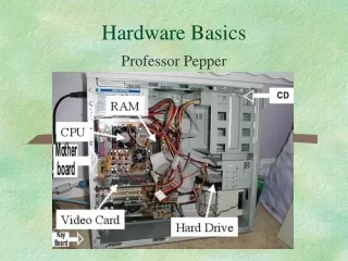
+ + - + - - Electricity • Electricity is the flow of electrons • Atoms contain • In the nucleus (center) • Protons with a positive charge • Neutrons with no charge (no consequence here) • “Orbiting” around the nucleus • Electrons with a negative charge + -
Charged Atoms • Atoms with more protons that electrons • Positively charged • Try to acquire additional electrons to get back in balance • Atoms with more electrons than protons • Negatively charged • Want to give up electrons to get back in balance • If you set up an imbalance, electrons will try to jump (flow) between atoms to correct this • This flow is electricity
Conductors and Insulators • Materials that allow electrons to flow easily are conductors • Most metals are good conductors • Materials that don’t allow electrons to flow easily are insulators • E.g., plastic, rubber, glass • Some materials can be influenced to change from conducting to insulating (a very useful property) • Semiconductors
+ + - - + - Basic Law of Charges • Like charges repel each other • Opposite charges attract each other • Exert a force • Can do work: e.g., move something
Charge • Charge is measured in Coulombs ( C ) • (A unit we won’t use much) • Measure of how many more protons than electrons in a substance • 1 Coulomb = 2.15 x 10¹⁸ excess protons 2.15 x 10¹⁸ extra electrons = -1 C
Electromotive Force(Voltage) • Charge has the ability to do work • A “potential” to e.g. move something in one direction or another • Difference in potential (in charge) provides a force: Electromotive Force (EMF): Voltage Extra electrons + EMF (voltage)
Flow of electrons Conductor • If this is a conductor then ½ the excess electrons will very rapidly flow to the other end to balance the charge Extra electrons + EMF (voltage)
Flow of electrons Conductor • If this is a conductor then ½ the excess electrons will very rapidly flow to the other end to balance the charge ½ the extra electrons 0 voltage
Flow of electrons Conductor • If this is a conductor then ½ the excess electrons will very rapidly flow to the other end to balance the charge • And then things are not very interesting ½ the extra electrons 0 voltage
Flow of electrons • If this is a conductor then ½ the excess electrons will very rapidly flow to the other end to balance the charge • And then things are not very interesting • Hence we set up circuits (cycles, loops) to keep this going
Flow of Electrons • “Current” is the flow of electrons • Measured in Amperes (Amp, or A) • 1A is 1 Coulomb of charge flowing past a point per second
Current vs. Voltage • Water analogy • Useful, but only goes so far • Coulombs analogous to quantity (gallons) • Amps analogous to flow rate (gallons / sec) • Voltage analogous to pressure (lbs/ft2)
Resistance • Can have a lot of flow at low pressure or a lot of pressure but low volume • Depends on the size of the pipe • Resistance is analogous to the size of the pipe • Resistance is the opposition to current flow • Measured in Ohms ( Ω )
Ohm’s Law • Relates current, voltage, and resistance • Current normally denoted by variable I • Voltage normally denoted by variable V • Resistance normally denoted by variable R V = I * R
V I R Ohm’s Law • V = IR • R = V / I • I = V / R
Ohm’s Law • In the electronics we will do, we tend to (try to) hold the voltage constant (or zero) • Typically 5v • starting to use 3.3v, but 5v still most common • I = V / R I = 5 / R • Raise the resistance, current drops • Lower the resistance, current rises
Ohm’s Law • I = V / R I = 5 / R • Raise the resistance, current drops • Lower the resistance, current rises • What happens if we lower the resistance towards zeros?
Ohm’s Law • I = V / R I = 5 / R • Raise the resistance, current drops • Lower the resistance, current rises • What happens if we lower the resistance towards zeros? • Current goes towards infinity • Power = V * I (related to heat) • Boom! (or Poof!)
Current Limiting • Important • This is how you (literally) fry hardware if you don’t pay attention (trust me, I know) • Always think carefully (and check!) that the path from 5v source • From power supply, or from output pin of a chip to ground (0v location) has appropriate resistance • Not a “short circuit” ~0Ω • Current limiting resistor at value needed to stay within current limits of the device
Aside: Units • Volts, Amps, Ohms • Normally use metric system unit prefixes mega M million 1,000,000 106 kilo k thousand 1,000 103 one 1 100 milli m thousandth 0.001 10-3 micro μ millionth 0.000 001 10-6 nano n billionth 10-9 pico p trillionth 10-12
Examples 5V with 10Ω 5/10 A = 0.5A = 500mA • For typical chips you will use = Poof! 5V with 100Ω 5/100 A = 50mA • Still Poof! 5V with 250Ω 5/250 A = 20mA • OK for PIC processors, not for lots of other digital electronics 5V with 10kΩ 5/10000 A = 0.5mA • Good for most digital electronics
Schematic Diagrams xx • Wire, connection, cross, hop-over • Resistor, variable resistor (pot, rheostat) • Battery, switch • Capacitor, electrolytic capacitor • Diode, LED • Transistor (PNP, NPN) • Inductor, transformer • Integrated circuit
AC vs. DC • DC – Direct Current • Current flows steadily in one direction • Most of what we will do is DC • AC – Alternating Current • Current flows in one direction then another • Wall current does this • Alternating 60 times per sec • 60 Hz V V
Capacitance • Capacitor • Device with two conducting plates separated by insulating material (called dielectric) • Stores electric charge in the dielectric • Water metaphor • Consider a pipe with a rubber balloon blocking it • DC current bulges out the balloon (charges the capacitor) • But then stops flowing • Release the pressure the charge drains back out over time • AC current can go back and forth continuously • Capacitor blocks DC but allows AC to pass
Capacitance • Capacitance is measured in Farads ( F ) and denoted by variable C • Amount of charge divided by voltage across plates • Charge (in Coulombs) denoted by Q • C = Q / V
Series and Parallel Circuits • Series circuit • Parallel circuit
R1 R2 R1 R2 Series and Parallel Circuits • Combining resistors • Rtotal-series = R1 + R2 • Rtotal-par = (R1 * R2) / (R1 + R2)
C1 C2 C1 C2 Series and Parallel Circuits Combining capacitors • Ctotal-series = (C1 * C2) / (C1 + C2) • Ctotal-par = C1 + C2
Digital Electronics • Computer circuits treat signals as digital values • Consider signals to only have two states: 1 or 0 • +5v is considered to be “1” • 0v is considered to be “0”
Digital Electronics +5v • But need to leave some room for error or fluctuation • Between VHMin and +5v considered 1 • Between 0v and VLmax considered 0 • Between VLmax and VHMin is undefined (and unpredictable) • Can pass through this but you don’t want to stay there long 1 VHMin ?? VLmax 0 0v