Download
1 / 9
90 likes | 94 Views
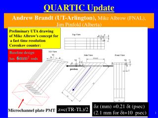
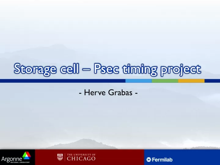
Storage cell – Psec timing project. - Herve Grabas -. Cell principle. We use a source follower structure. The polarization tension Vpol gives the drop of tension between Vin and Vout. An additional capacitance is added at the entrance of the Nfet for noise limitation (kT/C).

E N D
Storage cell – Psec timing project - Herve Grabas -
Cellprinciple We use a source follower structure. The polarization tension Vpol gives the drop of tension between Vin and Vout. An additional capacitance is added at the entrance of the Nfet for noise limitation (kT/C). Characteristics : Nfet : 300nm x 6.5µm Capacitance : 20 fF Vpol = 400mV
Input switch Sampling cap Read switch Mux trigger/sampling
Results : DC Charac Big drop of tension due to the source follower: 500mV The output dynamic is consequently reduced Output dynamic: 700mV
Results: Bandwidth Cutoff frequency: 4GHz (prelayout) Ron = 1.2kW Cin = 15fF + 17fF This is only for one cell. Have to be checked for 125 cells. If bandwidth issue Ron can be reduced a bit more. But then beware of leakage current at the input.
Layout dimensions Previous layout: dimension should remain the same Input switch Input Nfet Storage capacitance
Bandwidth • Input bandwidth and signal: Actually we put the input signal on 64 cells witch means : • f_3dB = 1/2.pi.Z.Ctot Z= 50 Ohms Ctot = 125*Cd (off) + 64*Csto Cd = 500aF & Csto = 40fF • Cd appears to be small enough
Input lines • Layout of the input lines • To reduced reflexion we want a 50 Ohms impedance for the line. • 50 Ohm matching is possible using 2 layers of metal with a given width.
Leakagecurrent • Leakage current • Target: 4µs window for digitization. • Due to the process used the leakage current at the input is relatively high. • Using a Rd switched allow us to have an output stable even with a leaking input.