Download
1 / 33
330 likes | 334 Views
Read More about - Introducing a 10-nm Particle Counter for Ultrapure Water<br>

E N D
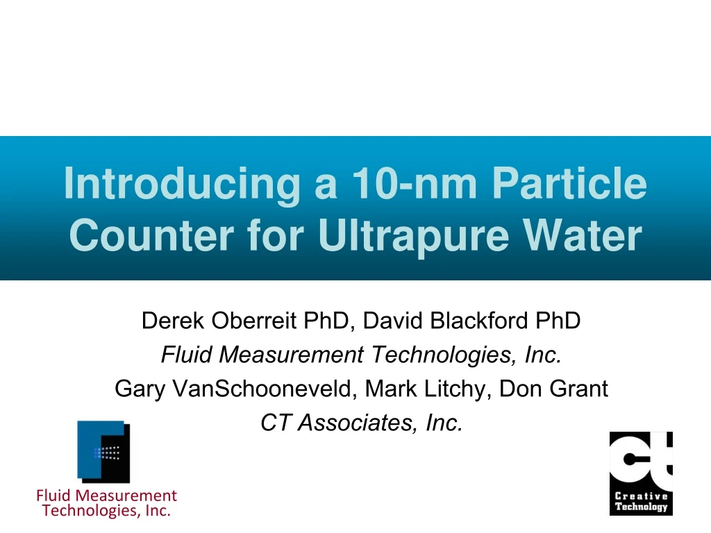
Introducing a 10-nm Particle Counter for Ultrapure Water Derek Oberreit PhD, David Blackford PhD Fluid Measurement Technologies, Inc. Gary VanSchooneveld, Mark Litchy, Don Grant CT Associates, Inc. Fluid Measurement Technologies, Inc.
Outline • Overview of the state of the art in in-situ particle counting Overview of particle counting in the gas phase Description of threshold particle counting Description of the Scanning Threshold Particle Counter (Scanning TPC) Review of sample data • • • •
Can existing technology get us here?
Liquid Particle Counting Technologies • Dynamic light scattering – Requires high concentrations Optical particle counting – Specified down to 25nm with 3-5% detection efficiency – Sensitive to particle composition Acoustic Coaxing Induced Microcavitation – Able to detect 20nm particles – Commercial availability unknown Nebulization – Promising new technology to provide measurements at previously unattainable size thresholds • • • – Aerosolization – Condensation Particle Counting
Particle analysis in the gas phase • John Aitken, in 1888, showed a method for detecting and counting optically invisible, nanometer size aerosol particles by enlarging them via heterogeneous condensation of a supersaturated vapor http://www.iara.org/AerosolPioneers.htm
Condensation particle counting… the science • Supersaturated vapors (relative humidity greater than 100%) are not happy The vapor wants to leave the gas phase and condense onto a surface • W=σdA • Curved surfaces are energetically less favorable due to added surface tension work (Kelvin effect) • Condensation onto particles is a function of the surface radius and the degree of supersaturation
Condensation particle counting more science • The particle radius threshold at which a supersaturated vapor will condense onto its surface is given by T k B S=Scritical,r r 2 V P vapln o r P where γ Vm is the molecular volume of the condensing liquid. Po pressure above a flat surface of the condensing vapor and P actual vapor pressure P/Po is the Saturation Ratio, S Varying the degree of S the minimum enlarged particle size is the surface tension and is the vapor is the • • changes
Condensation Particle Counting how it is implemented • Lewis number is the ratio of the thermal diffusivity of a gas λ, to the mass diffusivity of a vapor D, Le= λ/ D Le < 1 (e.g. water in air), cold saturated gas introduced to warm wet walls will drive vapor into gas faster than heat, leading to S>1 Le > 1 (e.g. butanol warm saturated gas introduced to cold walls will pull heat out of the gas faster than butanol vapor, leading to S>1 • • in air), TSI Incorporated 3772 CPC Brochure
A note on detection efficiencies • OPCs shallow detection efficiency curve Many OPCs are specified at less than 5% detection efficiency Condensation Particle Counters (CPCs) are specified at their 50% cutoff have a Detection Efficiency Comparison between in-situ OPC and CPC 3772 CPC 50% Detection Efficiency at 10 nm • • OPC data provided by Particle Measuring Systems. 3772 CPC Data by CT Associates
Scanning Threshold Particle Counter (Scanning TPC) Principle of Operation Non-volatile Residue Monitor Threshold Particle Counter UPW Size Selective Condensation Growth Large Droplet Removal Optical Detection Nebulization Evaporation
ScanningTPC Principle of Operation • Size selective growth – All particles entering Condensation Particle Counter (CPC) are optically ‘invisible’ – Particles larger than a threshold size will grow by orders of magnitude through vapor condensation – Threshold size can reach as low as 1 nm! – Scanning through different threshold diameters leads to a cumulative size distribution Non-volatile residue limits lowest threshold diameter setting • Non-Volatile Residue Particles Colloid Particles Particle Diameter Size Selective Condensation Growth
ScanningTPC Principle of Operation • Stepping threshold diameter range currently 10 nm to 30 nm Lower threshold diameters possible with low residue UPW Higher threshold diameters also possible 100% Detection Cumulative #/mL Channel 1 Non-Volatile Residue Particles Colloid Particles Particle Diameter Diameter Aerosol Particle Concentration 100% Detection • Cumulative #/mL Channel 2 Non-Volatile Residue Particles Colloid Particles Diameter • Particle Diameter 100% Detection Cumulative #/mL Channel 3 Non-Volatile Residue Particles Colloid Particles Diameter Particle Diameter
Scanning TPC Nebulizer Design Secondary large droplet removal incorporated downstream of nebulization Predicted particle sizes (150, 300, 600 ppt) region 1.E+03 1 0.9 0.8 0.7 Percent detected by 3772 S TPC 0.6 S TPC S TPC LNS #6 dN/dlogDp 1.E+02 0.5 LNS #6 LNS #6 Det eff 0.4 0.3 0.2 0.1 1.E+01 0 1 10 100 Size (nm) Upper tail of droplet distribution removed to minimize dissolved non-volatile residue particle counts
Scanning TPC Response to dissolved NVR • High levels of DNVR will lead to false particle counts Plot shows little sensitivity to low levels of added NVR (some true colloidal particles will be present due to injection system and impurities in the KCL) Scanning TPC Response to injected KCL • 1.E+10 > 10 nm > 15 nm > 20 nm Reported particle counts (#/ml) 1.E+09 1.E+08 1.E+07 1.E+06 1.E+05 0.1 1 10 100 1000 10000 100000 Dissolved NVR over 150 ppt background (ppt)
Offline Data Inversion Option 100% Detection • Monte-Carlo method may be used to estimate the true particle size distribution Accounts for shape of detection efficiency curve Accounts for shape of droplet size distribution Finds best fit of a defined colloid size distribution to match measurements Cumulative #/mL Channel 1 • D50 Diameter Particle Diameter TPS Data Inversion Example TPS Data Inversion Example • 4.0E+06 4.0E+06 3.5E+06 3.5E+06 3.0E+06 3.0E+06 Measured values Inverted values Inverted values Measured values 2.5E+06 2.5E+06 • #/ml #/ml 2.0E+06 2.0E+06 1.5E+06 1.5E+06 1.0E+06 1.0E+06 5.0E+05 5.0E+05 0.0E+00 0.0E+00 0 0 5 5 10 10 15 15 20 20 25 25 30 30 35 35 Particle Diameter Particle Diameter
Scanning TPC Sample Data Colloid Size Standards • High concentration solutions of colloidal silica and gold nanoparticles prepared for testing Size distributions of each of the solutions has been characterized using Liquid Nanoparticle (LNS) technology – provide high purity, online dilution. • Sizing US Patents 8,272,253 and 8,573,034 Use LiquiTrak • Precision Diluter to ®
ScanningTPC Colloid Size Standards Sample Data 30 nm Silica 12 nm Silica 20 nm Silica 2.5e+15 8.0e+16 1.4e+17 1.2e+17 Differential number weighted distribution Differential number weighted distribution Differential number weighted distribution 2.0e+15 6.0e+16 1.0e+17 (d (#/mL) / d log(Dp)) (d (#/mL) / d log(Dp)) (d (#/mL) / d log(Dp)) 1.5e+15 8.0e+16 4.0e+16 6.0e+16 1.0e+15 4.0e+16 2.0e+16 5.0e+14 2.0e+16 0.0 0.0 5 10 20 30 40 50 5 10 20 30 40 50 5 10 20 30 40 50 Particle Diameter (nm) Particle Diameter (nm) Particle Diameter (nm) 3.0e+12 4.0e+14 30 nm Gold 40 nm Gold Differential number weighted distribution Differential number weighted distribution 2.5e+12 3.0e+14 (d (#/mL) / d log(Dp)) (d (#/mL) / d log(Dp)) 2.0e+12 1.5e+12 2.0e+14 1.0e+12 1.0e+14 5.0e+11 0.0 0.0 5 10 20 30 40 50 5 10 20 30 40 Particle Diameter (nm) Particle Diameter (nm) Data provided by CT Associates using Liquid Nanoparticle Sizing methodology
ScanningTPC Sample Data Sensitivity • Threshold diameter set to 10nm The system responds to all particles with an attenuated response for the 12 nm particles 10nm Threshold Diameter 1E8 #/mL Colloidal Silica Injections 2.0E+08 • 1.8E+08 30nm 20nm 1.6E+08 1.4E+08 12nm Particles/mL 1.2E+08 1.0E+08 8.0E+07 6.0E+07 4.0E+07 2.0E+07 0.0E+00 12:21 12:28 12:36 12:43 12:50 12:57 13:04 13:12
ScanningTPC Demonstration Sensitivity • Threshold diameter set to 20nm The system shows little or no response to the 12nm particles, attenuated response to the 20nm particles and 80% detection of 30 nm particles. 20nm Threshold Diameter 1E8 #/mL Colloidal Silica Injections • 2.0E+08 1.8E+08 1.6E+08 1.4E+08 Particles/mL 1.2E+08 30nm 1.0E+08 20nm 8.0E+07 6.0E+07 4.0E+07 12nm 2.0E+07 0.0E+00 11:16 11:24 11:31 11:38 11:45
ScanningTPC Scanning Operation Sample Data • Operated TPC in mode that steps through threshold particle diameters Mixture of 12, 20, and 30 nm particles at equal concentrations Scanning Mode 1E8 #/mL Mixed Colloidal Silica Injection 1.8E+08 1.6E+08 10nm 1.4E+08 Particles/mL 1.2E+08 15nm 1.0E+08 • 8.0E+07 6.0E+07 20nm 4.0E+07 2.0E+07 0.0E+00 17:25 17:28 17:31 17:34 17:36 17:39 17:42 17:45 17:48 17:51
ScanningTPC Sample Data UPW Monitoring • Instrument installed on small scale, semiconductor grade UPW system at CT Associates Good stability observed Distribution of particle sizes apparent Large scale UPW systems ~4X lower UPW System Monitoring 1.E+07 Particle Concentration (#/ml) • 1.E+06 • > 10 nm > 15 nm > 20 nm • 1.E+05 0:00:00 2:24:00 4:48:00 7:12:00 9:36:00 12:00:00 14:24:00 Time
Scanning TPC Filter Testing • Single channel mode >10 nm Shows material dependent retention of 30 nm particles 30 nm Rated Water Filter Challenged with 2E8 #/ml ( 6ppm) 30nm Particles 100 80 • Retention (%) 60 40 Silica PSL Gold 20 0 0.000 0.025 0.050 0.075 0.100 0.125 0.150 0.175 0.200 Fractional coverage (Monolayers)
Scanning TPC Pros and Cons • Pros – – – Cons – Low sample volume rate (~1 μl / min) – – dissolved non volatile residue Particle composition independence No dependence on refractive index or particle shape Wide dynamic range • Requires Butanol Lower threshold limit is sensitive to amount of as a consumable
Further development • • Increase inspection volume Further characterization of operating parameters Refinement and automation of optional offline data inversion software •
FMT Model 1000 LiquiTrak® Scanning TPC • • Internal data logging Touchscreen – Set nebulizer temperatures – Monitor and log pressures and temperatures – Adjust minimum detected particle size – Display particle counter concentration and trend lines – Set scan rates Patent pending display •
Thank you Questions?
Bibliography Grant DC (2008). “A New Method for Determining the Size Distribution of the Working Particles in CMP Slurries,” presented at the 2008 CMP Users Conference, sponsored by Levitronix. Don Grant and Uwe Beuscher (2009), “Measurement of Sub-50 nm Particle Retention by UPW Filters”, Ultrapure Water Journal, 26(11):34-40. Blackford D and DC Grant (2009). “A proposal for measuring 20-nm particles in high-purity water using a new technology,” Ultrapure Water, January 2009. Grant DC, DC Chilcote from UPW by a combination of Ultrafiltration Cartridges,” Ultrapure Water Journal, May/June 2012. and U Beuscher (2012). “Removal of 12 nm particles Modules and Microfiltration Rastegar, A (2013). “Particle Control Challenges in UPW ”, presented at 2013 UPW Micro Conference Patents US 8,272,253; US 8,573,034; US 7,852,465; Other patents pending
Scanning TPC Long Term Stability System Background - 2014 6e+6 Filter test system Upper 95% CL Mean Lower 95% CL 5e+6 Concentration (#/mL > 10nm) 4e+6 3e+6 2e+6 1e+6 0 01/06/14 01/20/14 02/03/14 02/17/14 03/03/14 03/17/14 03/31/14 Date
ScanningTPC Material Independence Sample Data • Inject 30 and 40 nm colloidal gold nanoparticles Response similar to colloidal silica 20nm Threshold Diameter Colloidal Gold Injections 2.0E+08 1.8E+08 1.6E+08 1E8 #/mL 40 nm Gold 1.4E+08 Particles/mL 1.2E+08 • 5E7 #/mL 30 nm Gold 1.0E+08 8.0E+07 1E7 #/mL 30 nm Gold UPW 6.0E+07 4.0E+07 2.0E+07 0.0E+00 12:28 12:43 12:57 13:12 13:26 13:40 13:55 14:09 14:24 14:38
ScanningTPC Sample Data Linearity • Dilution ratios varied over a 16X range Linearity 30nm Colloidal Silica challenge 1.2E+02 y = 3E-07x + 16.846 R2 = 0.9958 CPC Particles / cm^3 1.0E+02 8.0E+01 6.0E+01 4.0E+01 2.0E+01 0.0E+00 0.0E+00 1.0E+08 2.0E+08 3.0E+08 4.0E+08 Particle Injection concentration (#/mL)
Scanning TPC Single Channel Performance Installation of Ultra Filters at a Semiconductor Facility
Scanning TPC Single Channel Performance Resin Rinse Down Particle Rinse Non-volatile Residue Rinse 1e+9 10000 Cumulative Particle Concentration Added Resin A Resin B Resin C Resin D Resin E Resin F Spool Resin A Resin B Resin C Resin D Resin E Resin F Spool Non-volatile residue added (ppt) 1e+8 1000 (#/mL > 10 nm) 1e+7 100 1e+6 1e+5 10 1 10 100 1000 1 10 100 1000 Flush Volume (liters UPW) Flush Volume (liters) Data prepared and presented by CT Associates to the SEMI Ion Exchange Task Force on 02/27/2014