Download
1 / 25
510 likes | 1.09k Views
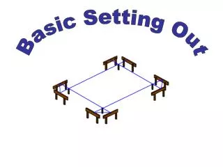
Setting-out of buildings and land survey for construction industry. Setting-out of a building – marking of a building position, size and shape in terrain. Setting-out plan – plan where a projected building is drawn and numeric values of setting-out elements are written.

E N D
Setting-out of buildings and land survey for construction industry Setting-out of a building – marking of a building position, size and shape in terrain. Setting-out plan – plan where a projected building is drawn and numeric values of setting-out elements are written.
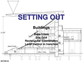
Land survey for setting-out: • creation of a setting-out net (measurement, calculation and marking of survey stations which can be used for setting-out) • setting-out of the spatial position of a building = setting-out of the building main position line (= frontage), setting-out of the axis or the main points of a linear structure (road, railway, watercourse) • detailed setting-out = setting-out of a building size and shape.
Setting-out nets: • planimetric networks – an aligning base, a traverse or an orthogonal setting-out net. The net is usually connected to points of S-JTSK (the coordinate system of Křovák’s projection). • altimetric networks –either independent of the planimetric network or the points of the planimetric network are used.
Setting-out accuracy is given and it is judged according to the standards: • ČSN 73 0420 – 1: Accuracy of setting out of constructions. Fundamental requirements. • ČSN 73 0420 – 2: Accuracy of setting out of constructions. Setting out deviations.
Setting-out of a position 1. Setting-out of an angle 2. Setting-out of a point position 3. Setting-out of a straight line 4. Setting-out of a circular arc
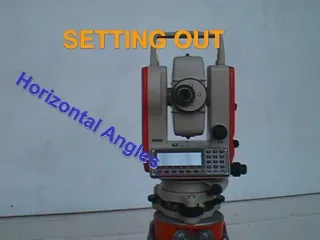
1. Setting-out of an angle 1. 1 Setting-out of a general angle - by means of a theodolite or a total station task: horizontal angle ω should be set out at the survey station S from point A
Procedure • centering and levelling of the instrument at the survey station S • pointing at A in the face left position of the telescope and horizontal circle reading • adding the angle ω to this reading and „setting“ calculated value by means of the alidade turning • marking of point B´ in this direction in required distance d (if high accuracy is not necessary result) • if high accuracy is demanded, setting-out of the angle has to be repeated in the face right position of the telescope and point B´´ is marked. In the middle of points B´and B´´ B (result).
by means of a theodolite by means of a pentagonal double prism (if high accuracy is not demanded) 1.2 Setting-out of the right angle
images of the range poles at points A and C have to create one vertical line in the field of view of the pentagonal prism then the prism is above point B • the range pole at point D (it is observed by eye closely above or under the prism) has to be in the same vertical line • angular accuracy of the setting-out is 0,04 gon, therefore the prism is used for the maximum distance 40 m
2. Setting-out of a point position 2.1 setting-out from rectangular coordinates, 2.2 setting-out from polar coordinates, 2.3 setting-out of a point by forward intersection, 2.4 setting-out of a point as the intersection of two straight lines.
2.1 Setting-out from rectangular coordinates Task: setting-out of the building main position line defined by points A and B. Rectangular coordinates xA, xB, yA, yB in reference to a part of setting-out network given by points 1 and 2 are known.
Thefootof a perpendicular A´ is set out by meansof a theodoliteat point 1. Point A´ is in the distance xAfrom point 1. This distance iscalledstationinganditismeasured by a tape. Therightangleis set out by a theodoliteat point A´ and distance yA (calledoffset) ismeasured by a tape. Thesameprocedureisusedforsetting-outof point B. Ifhighaccuracyis not demanded, points A and B canbe set out by meansof a pentagonal double prismand a tape.
setting-out elements = the horizontal angles A, B and the horizontal distances dA, dB • the procedure of horizontal angles setting-out is described in 1.1 (setting-out of a general angle) • this is the most frequent method of setting-out of a point position especially if a total station is available
Calculation of polar setting-out elements using coordinates Given: rectangular coordinates of points P1, P2 and P3: P1 – survey station, P2 – orientation point, P3 – point which is set out. Calculate: horizontal distance d13, horizontal angle 1
First of all the bearings σ12 and 13 are calculated using coordinates of the points P1, P2 and P3 (see lecture 2). The thehorizontal angle 1: 1 = 13 – 12 . The horizontal distance d13:
2.3 Setting-out of a point by forward intersection Setting-out elements = the horizontal angles 1 and 2. Two theodolites placed at the survey stations 1 and 2 are used for setting-out.
2.4 Setting-out of a point as the intersection of two straight lines A set-out point is the intersection of two lines of sight which connect permanent marked points.
points A, B, C, D are set out by one of the previously mentioned methods • so-called berms (boards nailed up to stakes) are established so that they cannot be demaged by building operations • a wire is stretched across points AB, AD etc. and points A´, A´´ etc. are marked by notches at berms • when earthwork is realized, points A, B, C, D can be set out anytime quickly in the intersections of particular straight lines
3. Setting-out of a straight line 3.1 Setting-out of intermediate points if the end points A and B are accessible and mutually visible.
high accuracy is required intermediate points are set out by a theodolite placed at one of the end points • high accuracy is not necessary the end points are marked by range poles and the observer stands to extended straight line (several metres behind the range pole at A). Then the observer places a lineman (helper) with a range pole to the alignment of points A and B.
3.2 Setting-out of intermediate points if the end points A and B are inaccessible and if they are not mutually visible
Point C1 is chosen approximately in the straight line AB andit is marked by a range pole. Points A and B have to be visible from the point C1. A lineman with a range pole is placed by sight to the straight line C1 B and point D1 is marked. Then the range pole from the point C1 is placed by sight to the straight line D1 A and point C2 is marked. Then a range pole is placed by sight to the straight line C2 B and point D2 is marked. This procedure is repeated till the points C a D lie in the straight line AB.
3.3 Extension of a straight line • by turning of the telescope of the theodolite around the horizontal axis (horizontal rough clamp is tightened) • by setting-out of the straight angle