Download
1 / 23
430 likes | 988 Views
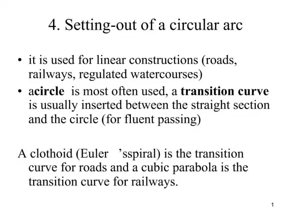
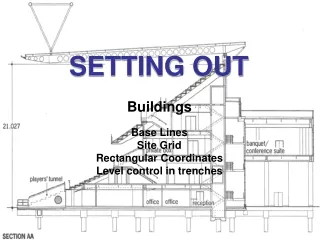
Basic Setting Out. Determining the Building Line A building square is positioned against the rear of the kerb, beyond the corner mark indicated on the kerb. The dimension is then taken from the back edge of the kerb keeping the tape running parallel with the builders square.

E N D
Determining the Building Line A building square is positioned against the rear of the kerb, beyond the corner mark indicated on the kerb. The dimension is then taken from the back edge of the kerb keeping the tape running parallel with the builders square. A wooden peg is then driven into the ground and the exact dimension is marked by a nail in the top of the peg. Corner of building marked on kerb X End of tape against back edge of kerb X
Determining the Building Line Positioning peg Z can be done in the same way as peg X making sure that it is positioned beyond the length of the building. Z X
Determining the Building Line Once pegs X and Z have been positioned a Ranging line is fastened to the two nails in the pegs. The ranging line needs to be pulled taut between the pegs as this indicates the Building Line. Z X
Establishing the corner of the building. A line is then extended along the edge of the builders square and beyond the building line where the two lines intersect determines the front corner of the building. Z Builder's square positioned against kerb and aligning with the corner of the building mark on the kerb. X
Establishing the corner of the building. A peg (A) is driven in at the intersection of the lines and a nail in the top of the peg identifies the exact position of the intersection. This denotes the front corner of the building. Z A X A
Establishing the width of the building Z • The dimension for the width of the building • is measured from the nail in the top of peg A. • Peg B is driven in at the required measurement. • The exact measurement is identified by a nail in • the top of the peg B. B A X Note. For accuracy keep the tape taut.
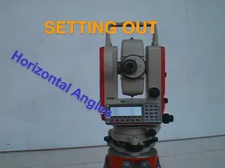
Setting out a right angle (corner of the building). Y Z B A Positioning Peg Y A builders square is positioned against the building line and lined up with the nail in the top of peg A a line is then pulled out to peg Y the line is to run parallel with the square creating a right angle. Peg Y is positioned beyond the required measurement of the building. X
An alternative method of setting out a right angle is to use the 3:4:5 method 5m 900 4m 3m
Identifying the dimension for the side of the building Y Z C B A A measurement is then taken to identify the width of the building a peg (C) is then driven in the exact measurement is then identified by a nail in the top of the peg. When peg C is positioned pegs X, Y and Z can be removed. X
Identifying the position of the final corner D C B Check the dimensions of the side of the building ( A-C). Transfer the measurement to the other side to (B-D) Drive in a temporary peg. A
Identifying the position of the final corner D C B Check the dimensions of the front of the building (A-B) then transfer the measurement to the rear this allows peg D to be positioned a nail can then be put in at the required measurements. A
Checking the diagonals D C B Measure and note the diagonal measurement (A-D). Now measure diagonals (B-C) and check against the (A-D) measurement. If the dimensions match this indicates that the corners are at right angles and the building is square. A
Checking the diagonals D C If one of the diagonals is longer than the other, the back two peg positions (C-D) will to be adjusted. Note large adjustments may require additional pegs to be located adjacent to pegs (C-D). B A
Checking the diagonals Small adjustments can be made by moving the nail/screw in the top of the peg. Move nails/screws by the same amount, in the same direction, to maintain the overall Dimension.
Checking the diagonals D C Correct setting out will indicated by identical diagonal dimensions. Check all dimensions are correct. All surplus pegs are removed, leaving the four corner pegs indicating the building position. B A
Building Position Four corner pegs indicating the building position.
Profile Boards Foundation Walling Overall widths of foundation trenches and walls are identified on profiles. The pegs are positioned on the inside of the profile board cross pieces. This prevents the line tension pulling the cross piece from the pegs.
Profile Boards Partly driven nails in the top ofthe cross piece Identify the wall and trench marks. But as an alternative to this saw cuts can be made into the cross piece.
Position of Corner Profiles Profiles should be positioned approximately 1.500m minimum away from the edge of the trench. The distance may need to be increased if a mechanical excavator is to be used for the excavation. 1.500 Min The cross pieces should be kept level. Future Foundation Excavation
Profile Boards Once the profiles are set the ranging line needs to be extended from the corner pegs and marked on to the profile.