Download
1 / 25
270 likes | 522 Views
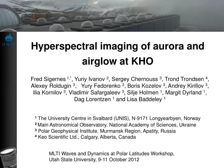
Hyperspectral imaging of aurora and airglow at KHO. Fred Sigernes 1,* , Yuriy Ivanov 2 , Sergey Chernouss 3 , Trond Trondsen 4 , Alexey Roldugin 3 , Yury Fedorenko 3 , Boris Kozelov 3 , Andrey Kirillov 3 ,

E N D
Hyperspectral imaging of aurora and airglow at KHO Fred Sigernes 1,*, Yuriy Ivanov 2, Sergey Chernouss 3, Trond Trondsen 4, Alexey Roldugin 3, Yury Fedorenko 3, Boris Kozelov 3, Andrey Kirillov 3, Ilia Kornilov 3, Vladimir Safargaleev 3, Silje Holmen 1, Margit Dyrland 1, Dag Lorentzen 1 and Lisa Baddeley 1 1 The University Centre in Svalbard (UNIS), N-9171 Longyearbyen, Norway 2Main Astronomical Observatory, National Academy of Sciences, Ukraine 3Polar Geophysical Institute, Murmansk Region, Apatity, Russia 4 Keo Scientific Ltd., Calgary, Alberta, Canada MLTI Waves and Dynamics at Polar Latitudes Workshop, Utah State University, 9-11 October 2012
THE KJELL HENRIKSEN OBSERVATORY – KHO 2008 - Location Summer view KHO 1) Instrumental module (30x) 2) Service Section 3) Platform More info at: http://kho.unis.no Prof. Dr 2 K. Henriksen
Instruments @ KHO TELESCOPE • IN ADDITION • Magnetometers • Scintillation receivers (GPS) • Riometer • Weather station • Web cameras
University Centre in Svalbard • University of Oslo • University of Tromsø • University of Alaska, Fairbanks • University College London • University of Wales Aberystwyth • University of Southampton • University of New Hampshire • Augsburg College • Tohoku University • National Institute of Polar Research Japan • Finnish Meteorological Institute • Embry Riddle Aeronautical University • Danish Meteorological Institute * • Air Force Research Laboratory * • Laboratoire de Planétologie de Grenoble • Institute of Radio Astronomy • AVINOR • The Polar Institute of China • The University of Electro-Communications Tokyo Institutions @ KHO The 10 Nations @ KHO … & excellent students!
PARTNERS @ LYR INTERNET KHO - UNIS – ARS - MINE 7
HYPERSPECTRAL IMAGING AT KHO Fiskeriforskning (1997) Inspired by SP3 (1993). Picture of the assembled Spextube Imagers. M is rotary table, T front surface mirror, L1 front lens, A 35mm camera lens adapter, O laser pointer, B barrel contains spectroscope, L3 camera lens, CCD camera head, I lift table, and E two steel bars. The FishTube spectrograph
AGF331 Remote Sensing and Advanced Spectroscopy (2000-07) Airspex 1 Imager (b) video camera (c) tripod (d) dome The Oriel FICS spectral imager Airspex 2 Imager – Swedish version! Experimental setup Dornier Dronespex I-IV
AURORAL LOW LIGHT HYPERSPECTRAL IMAGING? FS-IKEA ~14 days ? Electronic Machine Shops Purchase optics and mounts
The NORUSCA All-sky cameras Two NORUSCA II 1st Generation all-sky cameras (A) and (B). (1) Front element of all-sky lens, (2) 24 x 4 inch2 mount plate, (3) collimator lens tube, (4) lens mount, (5) ring holders, (6) filter box, (7) camera lens, and (8) EMCCD detector. Instrumental volume is ~ 65 x 18 x 16 cm3. Total mass is 8.9 kg. EMCCD detector: - PI ProEM 512B - 8.2 x 8.2 mm2 -70 deg. air cooled - Back-illuminated; 90% QE
Optical layout and design of the NORUSCA II Camera • Lens mechanics and optical diagram of the NORUSCA II all-sky lens: • focusing mechanism and collimator lenses, (2) filter box - chamber, • (3) camera lens, and (4) camera head.
The NORUSCA II Point Spread function Resolution: ~ 60 lp/mm
Filter: Liquid Crystal Tunable Filter (LCTF) (Cambridge Research & Instrumentation, Inc.). Spectral tuning is obtained by using electronically controlled liquid crystal wave plates to a Lyot filter design*. The wave plates behave as optical birefringent elements with an electrically variable retardance. Retardance is termed the optical path difference between the ordinary and extraordinary rays passing through a birefringent element. The latter is controllable due the effect that the liquid crystal molecules are orientation sensitive to electric fields applied between the plates. Since the retardance is directly linked to wavelength, the filters are tunable. Our filter: 400–720nm FWHM=7nm @ 550nm *P. J. Miller, “Use of Tunable Liquid Crystal Filters to Link Radiometric and Photometric Standards”, Metrologia 28, 145 – 149 (1991).
System performance 1. Focus tests Crossed scatter plots work best Source: 1 mm diameter pinhole @ 1m
System performance 2. Mapping function • Source: • 1 mm diameter pinhole • Schott NG9 • Distance = 1m • Rotation in steps of 10 deg. 2nd order polynomial fit: Note: R is forq > 30º in-between the mapping functions of an equal area and an orthographic fisheye lens, and its maximum Rmax = 4.08 mm at q = 90 º matches the size of the EMCCD.
System performance 3. Spectral characteristics - center pixel! [mW m-2 nm-1] [R s CTS-1]
System performance 3. Spectral characteristics – auroral emissions The minimum detection threshold signal is assumed to be 3 times the dark noise level, or 3s = 150 CTS/s. For the green [OI] 557.7 nm emission, the minimum detection limit then becomes 550 R.
First Samples Composite RGB color image. Red (R) 636.4 nm, green (G) 557.7 nm and blue (B) 486.1 nm. Screen dump of raw data from the camera at 630 nm. View from authors office desk at UNIS. Exposure time 10 ms at gain 40. Or …
Samples HYPERSPECTRAL
Nightside aurora Media 1 Panel (A): Color composite image from the NORUSCA II camera 24th of January 2012 at 15:15 UT. Location is the Kjell Henriksen Observatory (KHO). The Red color component of the image is at center wavelength 630 nm, Green at 557.7 nm and Blue at 400.9 nm
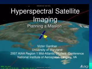
Dayside aurora Media 2 Panel (A): Color composite image from the NORUSCA II camera 29th of December 2011 at 08:55:00UT. Location is the Kjell Henriksen Observatory (KHO). The Red color component of the image is at center wavelength 630 nm, Green at 557.7 nm and Blue at 470.9 nm.
Concluding remarks (preliminary) • NORUSCA II: New hyperspectral all-sky camera (430 – 720 nm). • Wavelength element (filter): LCTF with FWHM = 7 nm @ 550 nm. • Novel C-mount NORUSCA II–E All-sky lens f/value=1.1. • Detects ~1/2 kR of auroral emissions in just 1 sec. • No moving mechanical parts to swap center wavelength. • It uses 50 ms to swap between 41 available center wavelengths. • Opens for new processing methods such as classification • The major disadvantage of the system is the low transmission of the LCTF, especially in the blue part of the spectrum.
Acknowledgement We wish to thank The Research Council of Norway through the project named: Norwegian and Russian Upper Atmosphere Co-operation On Svalbard part 2 # 196173/S30 (NORUSCA2).