Download
1 / 1
10 likes | 106 Views
Subcooling a Fujitsu 15RLS2 MSHP Samuel M. Prentiss, Matt D. H. Strong, Bruce L. Tuttle Advisors: Michael Peterson Ph.D , James C. LaBrecque. Installation on Campus

E N D
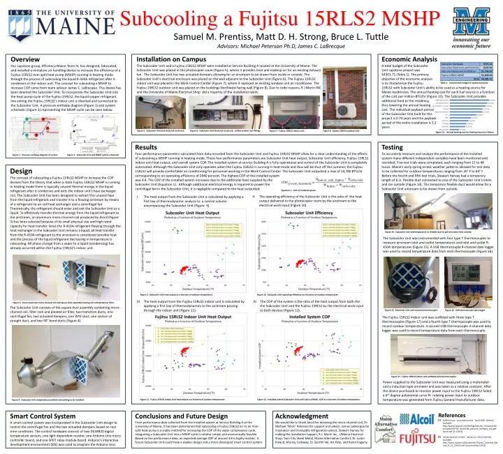
Subcooling a Fujitsu 15RLS2 MSHP Samuel M. Prentiss, Matt D. H. Strong, Bruce L. Tuttle Advisors: Michael Peterson Ph.D, James C. LaBrecque Installation on Campus The Subcooler Unit and a Fujitsu 15RLS2 MSHP were installed at Service Building A located at the University of Maine. The Subcooler Unit was placed in the photocopier room (Figure 5), where it provides heat and makeup air for an existing exhaust fan. The Subcooler Unit has two actuated dampers allowing for an airstream to be drawn from inside or outside. The Subcooler Unit’s electrical enclosure was placed on the wall adjacent to the Subcooler Unit (Figure 6). The Fujitsu 15RLS2 indoor unit was placed in the Work Control Center (Figure 7), where it replaced an existing window unit air conditioner. The Fujitsu 15RLS2 outdoor unit was placed on the buildings Northwest facing wall (Figure 8). Due to code reasons, R J Morin INC and the University of Maine Electrical Shop did a majority of the installation work. Economic Analysis A total budget of the Subcooler Unit capstone project was $4301.71 (Table 1).The primary objective of the economic analysis is to characterize the Fujitsu 15RLS2with Subcooler Unit’s ability to be used as a heating source for Maine residencies. The annual heating cost for each fuel source is a function of the cost per million-BTU/hr (Figure 13). The Subcooler Unit provides additional heat to the residency, thus lowering the annual heating cost. The individual payback period of the Subcooler Unit built for this project is 0.74 years and the payback period of the entire installation is 3.2 years. Overview Our capstone group, Efficiency Maine Team IV, has designed, fabricated, and installed a miniature air handling device to increase the efficiency of a Fujitsu 15RLS2 mini-split heat pump (MSHP) running in heating mode through the process of subcooling the liquid R-410A refrigerant after it condenses in the indoor unit. The concept for subcooling a MSHP to increase COP came from team advisor James C. LaBrecque. This device has been deemed the Subcooler Unit. To incorporate the Subcooler Unit into the heat pump cycle of the Fujitsu 15RLS2, the liquid copper refrigerant line exiting the Fujitsu 15RLS2’s indoor unit is diverted and connected to the Subcooler Unit. A pressure-enthalpy diagram (Figure 1) and system schematic (Figure 2) representing the MSHP cycle can be seen below. Table 1. Summarized budget of capstone project. Figure 5. Subcooler Unit and electrical enclosure. Figure 6. Subcooler Unit electrical enclosure, carflex conduit and fittings. Figure 7. Fujitsu 15RLS2 indoor unit. Figure 8. Fujitsu 15RLS2 outdoor Unit. Figure 13. Annual heating cost for heating sources in Maine. Results Four performance parameters calculated from data recorded from the Subcooler Unit and Fujitsu 15RLS2 MSHP allow for a clear understanding of the effects of subcooling a MSHP running in heating mode. These four performance parameters are Subcooler Unit heat output, Subcooler Unit efficiency, Fujitsu 15RLS2 indoor unit heat output, and overall system COP. The installed system at service Building A is fully operational and control of the Subcooler Unit is completely automated. Although the Subcooler Unit only operates when the Fujitsu 15RLS2 is running in heat mode and thus will be shut off this summer, the Fujitsu 15RLS2 will provide comfortable air conditioning for personnel working in the Work Control Center. The Subcooler Unit outputted a max of 14,780 BTU/hr corresponding to an operating efficiency of 2940 percent. The highest COP of the installed system was 4.4. The COP of the installed system increases due to the additional heat supplied by the Subcooler Unit (Equation 1). Although additional electrical energy is required to power the centrifugal fan in the Subcooler Unit, it is negligible compared to the heat outputted. Testing To accurately measure and analyze the performance of the installed system many different independent variables have been monitored and recorded. Five test trials were completed, each ranging from 12 to 48 hours. Maine’s early spring erratic weather patterns allowed for test data to be collected for outdoor temperatures ranging from 26° F to 64° F. Before the fourth and fifth test trials, Stewart Harvey had a temporary length of 6 in. flexible duct connected to one of the Subcooler Unit’s inlets and ran outside (Figure 14). This temporary flexible duct would allow for a Subcooler Unit airstream to be drawn from outside. Figure 2. Subcooler Unit and MSHP system schematic. Figure 1. Pressure-enthalpy diagram of system. Design The concept of subcooling a Fujitsu 15RLS2 MSHP to increase the COP derives from the theory that when a stock Fujitsu 15RLS2 MSHP is running in heating mode there is typically unused thermal energy in the liquid refrigerant after it condenses and exits the indoor unit’s heat exchanger coil. The Subcooler Unit has been designed to extract this unused heat from the liquid refrigerant and transfer it to a flowing airstream by means of a refrigerant-to-air coil heat exchanger and a centrifugal fan. Theoretically, the refrigerant should enter and exit the Subcooler Unit as a liquid. To effectively transfer thermal energy from the liquid refrigerant to the airstream, an aluminum micro-channel coil produced by Alcoil (Figure 3) has been selected because of its small physical size and high rated capacity for heat transfer. Since the R-410A refrigerant flowing through the heat exchanger in the Subcooler Unit remains a liquid, all heat transfer from the R-410A refrigerant to the airstream is considered sensible heat and the process of the liquid refrigerant decreasing in temperature is subcooling. All phase change from a vapor to a liquid (condensing) has already occurred within the Fujitsu 15RLS2’s indoor unit. Equation 1. COP of installed system. The operating efficiency of the Subcooler Unit is the ratio of the heat output delivered to the photocopier room by the airstream to the electrical work input (Figure 10). The heat output from the Subcooler Unit is calculated by applying a first law of thermodynamic analysis to a control volume encompassing the Subcooler Unit (Figure 9). Figure 14. Subcooler Unit and temporary 6 in. flexible duct to pull airstream from outside. The Subcooler Unit was instrumented with four type T thermocouples to measure airstream inlet and outlet temperatures and inlet and outlet R-410A temperatures (Figure 15). A USB thermocouple 4-channel data logger was used to record temperature data from each thermocouple (Figure 16). Figure 9. Subcooler Unit heat output as a function of outdoor temperature. Figure 10. Subcooler Unit operating efficiency as a function of outdoor temperature. The heat output from the Fujitsu 15RLS2 indoor unit is calculated by applying a first law of thermodynamics to the airstream passing through the indoor unit (Figure 11). The COP of the system is the ratio of the heat output from both the the Subcooler Unit and the Fujitsu 15RLS2 by the electrical work input to both devices(Figure 12). Figure 3. Alcoil aluminum micro-channel coil and square duct assembly housing coil and pleated air filter. The Subcooler Unit consists of the square duct assembly containing micro-channel coil, filter rack and pleated air filter, two transition ducts, one centrifugal fan, two actuated dampers, one WYE duct, one section of straight duct, and two 90° bend ducts (Figure 4). Figure 15. Subcooler Unit and mounted thermocouple. Figure 16. USB thermocouple data logger. The Fujitsu 15RLS2 indoor unit was outfitted with three type T thermocouples (Figure 17) and a fourth type T thermocouple was used to record outdoor temperature. A second USB thermocouple 4-channel data logger was used to record temperature data from each thermocouple. Figure 17. Fujitsu 15RLS2 indoor unit outfitted with thermocouples. Power supplied to the Subcooler Unit was measured using a multimeter and a induction type ammeter and was taken as a relative constant. After the device purchased to monitor power input to the Fujitsu 15RLS2 failed, a 6th degree polynomial curve fit relating power input to outdoor temperature was generated from Fujitsu General manufacturer data. Figure 11. Fujitsu 15RLS2 Indoor Unit heat output as a function of outdoor temperature. Figure 12. Installed system (Subcooler Unit and Fujitsu 15RLS2) COP as a function of outdoor temperature. Figure 4. Subcooler Unit completely assembled and waiting to be installed. Smart Control System A smart control system was incorporated in the Subcooler Unit design to control the centrifugal fan and the two actuated dampers based on real time conditions. The control hardware consists of two DS18B20 digital temperature sensors, one light dependent resistor, one Arduino Uno micro controller board, and one SPDT relay module board. Arduino’s interactive development environment (IDE) was used to program the Arduino Uno. Conclusions and Future Design From performance data collected from the installed system at Service Building A at the University of Maine, it has been determined that subcooling a Fujitsu 15RLS2 air-to air mini-split heat pump is a viable method for increasing the COP of the vapor compression cycle. Integrating a Subcooler Unit into a MSHP cycle is relative simple and economically feasible. Based on the performance data, an expected average COP of around 3.8 is highly realistic. A future Subcooler Unit could have a sleeker design and a more developed smart control system. Acknowledgment We would like to thank Alcoil for donating the micro-channel coil, Dr. Michael “Mick” Peterson for support and advice, James LaBrecque for inspiration and invaluable refrigeration advice, Stewart Harvey for making the installation happen, R.J. Morin Inc., UMaine Electrical Shop, Twin City Sheet Metal, Maine Alternative Comfort, Dr. Justin Poland, Murray Callaway, Dr. SenthilVel, Art Pete, and Karen Fogarty. References [1] [2] DuPont Suva, "suva.dupont.com," April 2005. [Online]. Available: http://www2.dupont.com/Refrigerants/en_US/assets/downloads/k05718_Suva410A_pressure_enthalpy_eng.pdf. [Accessed 22 4 2014]. Fujitsu General Limited, "master.ca," 2014. [Online]. Available: http://www.master.ca/documents/7Fujitsu_Technical_Manual_9_12_15RLS2.pdf. [Accessed April 2014].