Download
1 / 11
160 likes | 479 Views
SWR Meter Session 3 Learn about Transformers and SWR Meters. I. Port 1. Port 2. +. F. V. Forward Waves on Transmission Lines Z L = Zo (Characteristic Impedance). Transmitter. Z L. Load. -. Z load = Zo (No reflected wave) Zo = 50 Ohms There is only a forward wave. V=+IZo

E N D
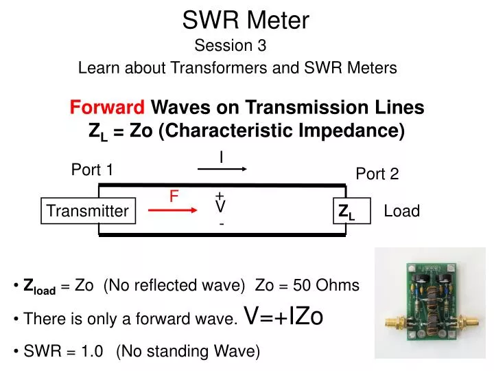
SWR MeterSession 3 Learn about Transformers and SWR Meters I Port 1 Port 2 + F V Forward Waves on Transmission Lines ZL = Zo (Characteristic Impedance) Transmitter ZL Load - Zload= Zo (No reflected wave) Zo = 50 Ohms There is only a forward wave. V=+IZo SWR = 1.0(No standing Wave)
SWR Meter I Port 1 Port 2 + R V ReverseWaves on Transmission Lines ZL = Zo (Characteristic Impedance) ZL Transmitter - • Here, ZL= Zo • There is only a reverse wave V=-IZo • SWR = 1.0 Current now reversed
SWR Meter I Port 1 Port 2 + F R V Normally ZL not Equal to Zo Forward and Reverse Waves on the Line Transmitter ZL Load - • ZL not equal to Zo • Standing Waves exist Forward wave reflects at load
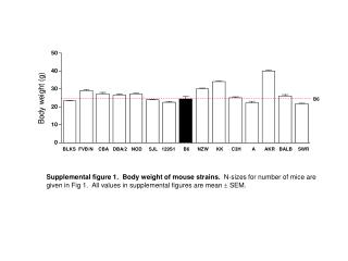
SWR Meter • Forward wave power always greater than reverse wave power • Forward wave power fixed for constant Tx Power • Reverse wave power = 0 for ZL = Zo • SWR 2:1 for ZL= 100 or 25 Ohms • Meter actual measures Voltage and Current on the line • SWR must be found from VFWD and VREVon the board Things to note in tests
Kits and Parts “meter” • T1 samples current • T2 samples voltage • RF appears at Diodes • Diodes act as detectors • Vrev and Vfwd measured • SWR Calculated or Meters Calibrated
Marking the Transformers Two Transformers Mark the red dots as shown This is arbitrary I set the dots on the single turn
Marking the Transformers • Set the other dots by inspection • This is not arbitrary
Ideal Transformers N1=N2Identical WindingsLenz and Faraday B1 Lossless 1 mA B1+B2 =0 1 mA ZL Lenz B2
SWR Meter Circuit…modified • Current in T1 Opposite direction for Forward and Reverse • R4, R3 balance the bridge • Add 33K resistors to J1,1 and J1,3 to J1,2 (ground)
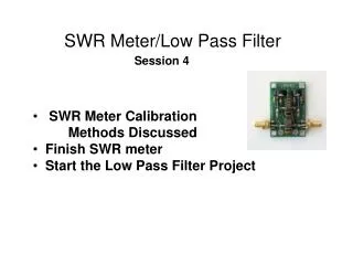
Measurements • Apply 2.5 Watts to RFin • Connect RFout to an open ckt • Note VFWD and VREV • Adjust R3 or R4 to set VFWD= VREV • Now measure VFWD and VREV For a 50,100 25 Ohm Load and a Short CKT • Record Data on supplied form Does the data make sense?
Meter measures voltages and currents • SWR calculated • Good example of Ferrite Transformers • Simple circuit has many limitations • Many examples on the WEB Summary sma connector with jumper