Download
1 / 20
250 likes | 818 Views
Radio Frequency (RF) Power / Standing Wave Ratio (SWR) Wattmeter. Design Team Members. Industrial Advisor: Martin F. Jue President of MFJ Enterprises Starkville, MS. Faculty Advisor: Dr. John P. Donohoe MSU ECE Professor. Team Leader: Chad Butler Email:

E N D
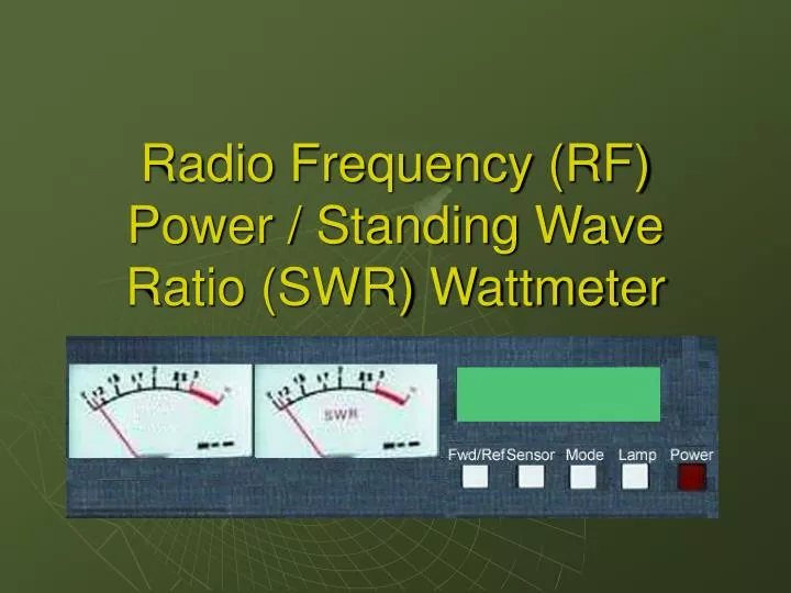
Radio Frequency (RF) Power / Standing Wave Ratio (SWR) Wattmeter
Design Team Members Industrial Advisor: Martin F. Jue President of MFJ Enterprises Starkville, MS Faculty Advisor: Dr. John P. Donohoe MSU ECE Professor Team Leader: Chad Butler Email: ceb9@msstate.edu Team Member: Timothy Garton Email: twg2@msstate.edu Team Member: Corey Amis Email: hca6@msstate.edu Team Member: John Kennedy Email: jwk7@msstate.edu
Problems with Current Models • Display • Current models do not have a combination of both analog meters and a LCD screen. • Power vs. Frequency • Current models are limited in the frequency range of power measurements. • Power Level • Current models are limited to only low power measurement.
Abstract • Directional Coupler • Forward Power • Reflected Power • (RF) Power / (SWR) Wattmeter Display Unit • Displays Forward and Reflective Power • Calculates and Displays SWR • LCD Display • Analog Display • 1.8MHz – 30MHz
SWR Analyzer Resistive SWR Bridge Built-in transmitter Displays SWR and frequency Connects to load SWR Wattmeter Directional coupler for real-time, in-line monitoring External transmitter Displays SWR and power Connects to a load and a transmitter Comparison with Senior Design II Project
Technical Design Constraints • SWR Accuracy: • Less than 10% when power is at or above 100 watts and SWR is below 3:1 • RF Power Accuracy: • Less than 10% of full scale • Voltage Regulation: • 12 – 18 volts produces 5 volts • Frequency Range: • 1.8MHz – 30MHz continuous range • Power Range: • Auto-ranging forward power measurements at 30, 300, and 3000 Watts • Auto-ranging reflected power measurements at 6, 60, and 600 Watts
Practical Design Constraints • Cost: • ≤ $125 • Dimensions: • 9” L x 12” W x 6” H • Power Requirements: • 12-18 volt DC source and will consume less than 1 amp of current • Protection: • High SWR indicator • Connections: • S0-239 (coaxial) • RJ-11 (telephone wire)
Prototype Design Components • Power Supply • Voltage regulated 5 volts • Analog Display Circuit • Forward and reflected power and SWR meters • LCD Display Circuit • Forward and reflected power and SWR numerical values and bar graph • Directional Coupler • Forward and reflected power • Microprocessor • Calculates SWR and runs displays
Block Diagram Directional Coupler Transmitter Display Unit Microprocessor SWR Power LCD
Software Interface Design(physical model) • LCD Display (3 Modes) • Forward power, reflected power, and SWR numerical readings. • SWR numerical reading and bar graph • Forward power and reflected power numerical values and bar graph Forward/Reflective Analog Power Meter Displays the forward and reflected power calculated by the microprocessor. SWR Analog Power Meter Displays the SWR calculated by the microprocessor. Sensor Switch Switches the input port. Mode Switch Switches the LCD between the three modes. Forward/Reflective Power Switch Controls the display on the forward and reflective analog power meter between forward and reflective power.
Coupler Options • Reflecto meter • Through-line principle • SWR resistive bridge • Strip-line directional coupler
Directional Coupler Testing 1. Measure forward and reflected voltages vs. frequency bands at: 1.8, 3.5, 7.0, 10.1, 14.0, 18.1, 21.0, 24.9, 28.0, and 29.4 MHz for 12.5, 50, and 200Ω loads 2. Calculate SWR for each point
16C76 Microprocessor Characteristics and Pin-out • Low-power RISC CPU at 20 MHz • 368 bytes RAM • 22 I/O ports • 5 channels of 8-bit A/D converter with 2 additional timers
Acknowledgements Special thanks to the following people: • Mr. Martin F. Jue, president of MFJ Enterprises • Dr. J. Patrick Donohoe, faculty advisor • Dr. Picone • Jordan Goulder