Download
1 / 13
250 likes | 713 Views
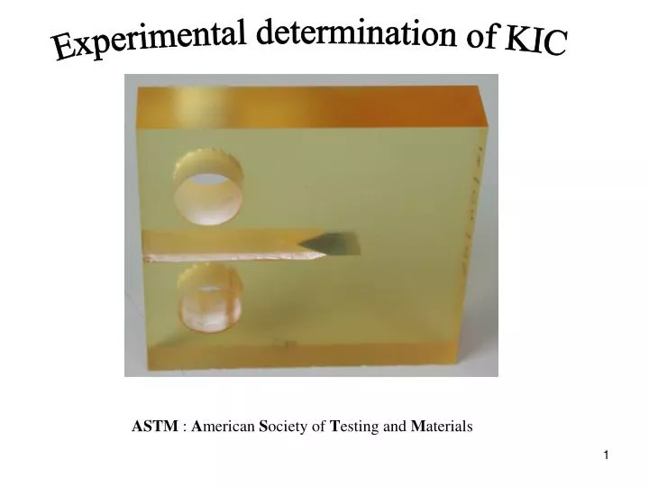
Experimental determination of KIC. ASTM : A merican S ociety of T esting and M aterials. Introduction:. K C. Specimen Thickness. Assuming a small plastic zone compared to the specimen dimensions,. a critical value of the mode-I SIF may be an appropriate fracture parameter.

E N D
Experimental determination of KIC ASTM : American Society of Testing and Materials
Introduction: KC Specimen Thickness Assuming a small plastic zone compared to the specimen dimensions, a critical value of the mode-I SIF may be an appropriate fracture parameter . KIC : plane strain fracture toughness plane stress plane strain KC : critical SIF, depends on thickness KI> KC : crack propagation KIC : Lower limiting value of fracture toughness KC Material constant for a specific temperature and loading speed
ASTM E 399 first standardized test method for KIC : - was originally published in 1970 - is intended for metallic materials - has undergone a number of revisions over the years - gives specimen size requirements to ensure measurements in the plateau region • ASTM D 5045 -99 is used here for plastic materials: Standard Test Methods for Plane-Strain Fracture Toughness and Strain Energy Release Rate of Plastic Materials Many similarities to E 399, with additional specifications important for plastics. • KI based test method ensures that the specimen fractures under linear elastic conditions confined plastic zone at the crack tip
1- Test specimens Two specimen configurations for D 5045 -99 : • Three Point Bend specimen (SENB): • Compact tension configuration (CT):
Plastic zone length c from Irwin Model (plane strain): For valid KIC measurements, the specimens are designed to ensure : - a small plastic zone size / specimen thickness B. - that plane strain conditions dominate around the crack tip. yield stress of the material for the temperature and loading rate of the test B must be sufficient to ensure plane strain. W-a must be sufficient to avoid excessive plasticity in the ligament. Plane stress condition if c = B From ASTM 399 Plane strain condition if c < B/25 Thus,
The theory considers an ideal plane crack with zero notch radius r Notch in reality The notch can simulate the theoretical crack 2- Precrack: • Remark: KC decreases with decreasing r until a limiting value rC 6.3 mm Below rC , KC approximately constant:
where W Alternatively, a2 W a2 B a1 a3 B a1 a3 • Chevron starter notch (see p4-26): The chevron forces crack initiation at its center. B W A sharp crack of length af is propagated by fatigue such that: Natural crack a0 a During fatigue the maximum SIF must not exceed 60 % of KIC The measured crack length a is the average of the crack lengths measured at: - the center of the crack front: a1 - the end of the crack front on each surface: a2 and a3 Measurements of B and W to 0.1% accuracy
B 90° Chevron • Laboratory specifications for the specimen W = 48 mm a0 = 0.45 W A A A-A
P(t) P(t) (N) 120 Crack front 30 P(t) Time 3- Experimental procedure • Expression for the calculation of the SIF (CT- configuration): f shape function for the CT specimen (see A2.5 p8) Accurate within ± 0.65% over the range KQ conditional or trial KIC value. • Fatigue crack propagation: half a day to complete 3 Hz
Test procedure: Servohydraulic testing system (Instron) used with constant displacement rate imposed. (see section 8.3) Loading rate and test temperature should be noted. Both displacement and load recorded simultaneity during the test. Several specimens tested (at least three) : reproducibility
4- Interpretation of test record and calculation of KIC Pmax : maximum load sustained by the specimen AB : initial compliance C = u / P AB’ : compliance 5% greater than AB Evaluation of PQ : PQ = Pmax Calculus of KQ Pmax within lines (AB) and (AB’): Pmax outside lines (AB) and (AB’): PQ = intersection of (AB’) and the load curve Pmax / PQ < 1.1 Calculus of KQ Pmax / PQ > 1.1 Test invalid
is equal to then Calculation of the trial value KQ with the relation : If moreover, When the test result fails to meet these requirements, use a 1.5 times larger specimen. (see 9.1.5) See Testing summary table 3 , p6. http://lmafsrv1.epfl.ch/Fracture_course2006/KIC%20testing/