Download
1 / 89
940 likes | 1.11k Views
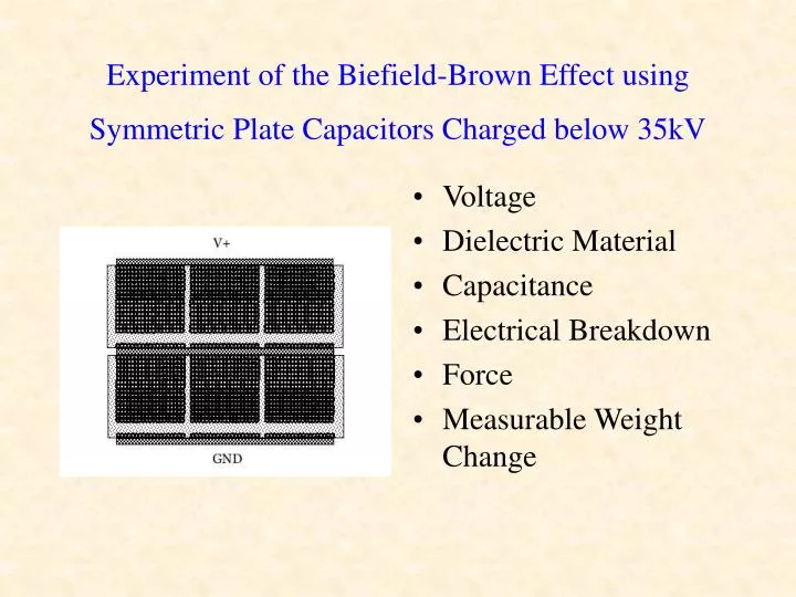
Experiment of the Biefield-Brown Effect using Symmetric Plate Capacitors Charged below 35kV. Voltage Dielectric Material Capacitance Electrical Breakdown Force Measurable Weight Change. Introduction: it has been suggested….

E N D
Experiment of the Biefield-Brown Effect using Symmetric Plate Capacitors Charged below 35kV • Voltage • Dielectric Material • Capacitance • Electrical Breakdown • Force • Measurable Weight Change
Introduction: it has been suggested… • There is a net thrust in the direction of the fixed positive electrode of a symmetric capacitor when a high voltage electric field is applied Dielectric Material • The force behind said thrust is/is not related to ionic wind • Thomas Townsend Brown [1] used +100kV in order to apply a measurable net thrust independent of the fixed distance between the two electrodes • Brown claimed to have used spherical lead electrodes, weighing 40 pounds each [1] and not plates; thus, this seems to the author a valid new approach to determine whether or not such effects (provided are accurate) really have anything to do with symmetry and high voltage electric fields • Numerous experimenters have demonstrated that asymmetric capacitors do indeed have such a net thrust • Is there is any measurable force using a solid dielectric material between the symmetric electrodes?
Hypothesis • I did not think there would be any considerable weight change of the symmetric capacitors • Because the various apparatuses I have read about that were built by the various experimenters since the time of Brown’s filed patents [12], those yielding measurable thrust, have always involved asymmetric capacitance of some form or another, usually with the cathode angled in line with the direction of charge toward the anode, and I suspect there is a significant reason for such designs.
Experimental Design: the capacitors • Four symmetric capacitors were constructed, each with different diameters • None of the symmetric capacitors had air dielectrics • Two were constructed having Styrofoam as a dielectric material with spacing well beyond the minimum electrical breakdown distance
Two other symmetric caps • Two of the symmetric capacitors had polystyrene as a dielectric material, • The electrodes separated very close (but slightly greater) than there minimum electrical breakdown distance
Five asymmetric caps • Five asymmetric capacitors were constructed as controls, the purpose being that at least some measurable weight change would be required in order to demonstrate that the setup used was acceptable • One asymmetric capacitor included a flat disc anode and a tungsten needle cathode separated by polystyrene
One particular asymmetric • An asymmetric capacitor was constructed of a conical brass cathode and an aluminum wire circling the perimeter
Adjustable asymmetric • An “adjustable” asymmetric capacitor was constructed of a bent piece of sheet aluminum anode and a tungsten needle cathode, having a Styrofoam dielectric • The adjustments were possible by changing the distance between electrodes, as well as the angles
Similar asymmetric • A similar asymmetric capacitor (but non adjustable), as that above, was also constructed with a polystyrene dielectric disc
The “Lifter” • Lastly, a triangular (“lifter”) asymmetric capacitor with an air dielectric was constructed, but not following any outside inventors’ specifications
Additional Design Notes • The electrode plates of all but the lifter and the conical capacitor were cut from a roll of aluminum flashing, the type used for duct work • The conical cathode of the asymmetric capacitor was constructed from a flat, circular sheet of brass with an 18 degree angled piece cut from edge to center, bent, soldered on the inside to maintain an even electrical contact from the edge to the center and then supported with glue (“Amazing E-6000”) on the outside • The conical cathode was attached to the Styrofoam using the same glue, but the glue was placed on the outside of the joint, rather than directly between the cathode and the Styrofoam, so as to utilize the dielectric constant of the Styrofoam only • The aluminum wire anode was also secured around the perimeter of the Styrofoam with glue, but only with dots in certain places in order to maintain the dielectric constant of the Styrofoam
Additional Design Notes (cont.) • All plates were drawn in circles with a compass and carefully cut out using tin snips • The plates edges were sanded down considerably and then buffed for smoothness • The symmetric plates were pressed in a 2-ton press in order to prevent buckling, in order to obtain as even as possible separation between the plates • The distance between the symmetric plates with a Styrofoam dielectric (the thickness of the Styrofoam disc) was 15/16”, which is a significantly greater distance than electrical breakdown (discharge between the plates) occurs for this material
Additional Design Notes (cont.) • The diameter of the Styrofoam discs between all the electrodes was chosen to be distinctly larger than the electrodes themselves, in order to rule out the transmission of ionic wind (with the exception of the “lifter”) • The plates were glued conservatively (in order to not alter the value of the dielectric constant significantly) to the Styrofoam and allowed to dry for 24 hours • The 28 AWG wire attached to the electrodes was accomplished with the following: 1) solder, then 2) glue, then sometimes 3) electrical tape for additional stability • 4 additional drops of glue were applied to the perimeter of the plates, attaching them securely to the Styrofoam and / or polystyrene
Experimental Design: the scale • A digital scale (with means to calibrate) with a 6” glass plate was used, rated sensitivity of 1g to 5kg • A PVC mount was constructed to hold the capacitors off the glass plate evenly at a distance of 1.5” and to hold the wire out of the way
Experimental Design: the Power Supply • A 35kV rated DC power supply was used • The supply attached to a transformer (12V, 3A), that in turn attached to the standard U.S. household AC current • The power supply required the use of an earth ground in the event the maximum voltage rating was exceeded, the unit discharged to it (and only discharged in such events)
Notes on the Power Supply • The power supply consisted of an air-gap safety discharge to send to this ground, that was adjustable • It is commonly known that the breakdown voltage distance for 30kV is inch, and since the unit was rated up to 35kV, the gap was adjusted to 1 3/16”
Notes on the Air Gap • It was noted that if the air gap discharged, then considerable time after was required to pass in order to allow the internal resistors to cool enough for the unit to meter the voltage accurately (in other words, the unit might discharge again at 10kV or less at 1” or more if the resistors were still hot) • The meter on the unit was originally designed for measuring micro amps, but was modified to read kilovolts, thus, if the meter read 30uA, it was assumed to be outputting 30kV
Experimental Design: the dielectric materials • Three different dielectric materials were used in the experiment: 1) air, 2) Styrofoam and 3) polystyrene • The dielectric constant of Styrofoam ~ 1.03… • The dielectric constant of polystyrene ~ 4 • The dielectric constant of air = 1 • It was determined after numerous discharge tests for the various materials, that the capacitor plates needed to be at least a certain distance r to avoid electrical breakdown up to 35kV, whereby capacitance would be lost: 1) for air, r 1.2”, 2) for Styrofoam r 3/16” and 3) for polystyrene r .005”
Assumptions • The power supply rating / meter is accurate within 5000 V • The glue between the aluminum plates and the Styrofoam does not significantly affect the dielectric constant with the amounts used • The precision of the disc cutouts are adequate to consider them symmetric • The distance between different points (perimeter, center, etc.) on the plates are even enough to not effect capacitance
Controls • Styrofoam and polystyrene were both used instead of air in order to rule out ionic wind • Five asymmetric capacitors were constructed in addition to the symmetric plate capacitors in order to see roughly how much weight change should be expected for a measurable reading • The distance between the plates is not too great (for the polystyrene capacitors), so as to not diminish the overall capacitance, which could in turn negate any effect, but large enough to prevent discharge • The diameter of the Styrofoam disc is larger by at least 0.5” than the discs they are sandwiched between, so as to prevent bowing and / or ionic air around the circumference to have any effect on the results
Controls (cont.) • The edges of the electrodes were sanded and plates pressed so as to have an even distance between them • All edges were buffed smooth so as to better prevent arcing (even invisible arcing) • The maximum sized discs at my disposal were used so as to create as large an electric field as possible for the desired effect, but still small enough to fit on the scale • The wire leads to the capacitors were taped down both near the power supply and near the scale, so as to not move or shift excessively during the measurements, so as to better prevent weight changes
Independent Variable • Changed the voltage applied to each capacitor for each of the iterations up to 35kV
Dependent Variable • Measured the weight of each capacitor
Data Collection: steps • Placed the mount on the glass plate of the scale • Turned on the scale, which auto-calibrates the weight to zero when turned on • Placed the finished capacitor onto the mount • Turn on the power supply to the required voltage • Weighed each capacitor in grams g
Preliminary notes • The two symmetric capacitors with the polystyrene dielectric arced from the edges, around the polystyrene disc dielectric material, despite this distance being a total of 1 ½”
Discharge remedy • Electrical tape was added to the design (from the edges of the aluminum discs, around the dielectric) for these, restricting any air discharge for the tests • The added weight of the electrical tape was accounted for in the results below
Experimental Results • Only two capacitors showed any weight changes with the experimental setup herein: C7 (the adjustable asymmetric capacitor) and C9 (the “lifter”) • Both capacitors’ changed weight demonstrated that it also was controllable with the voltage and many iterations were taken with those in order to rule out anything like the capacitors were shifting weight, as the changes in weight were considerably small • By turning the voltage up, the weight would change; by turning it back down, the weight would return to its original • C7 gained weight with its anode below the cathode • C9 lost weight with its anode above the cathode
Capacitor g @ 0-15kV g @ 15-25kV g @ 25-35kV C_1 32 32 32 C_2 49 49 49 C_3 31 31 31 C_4 33 33 33 C_5 18 18 18 C_6 26 26 26 C_7 20 21 22 C_8 24 24 24 C_9 42 42-41 41 Table 1: capacitor weight changes
Additional notes on C7 • C7 was the adjustable asymmetric capacitor • The results were taken at various angles, placements and distances sporadically, some yielded no weight changes, others less or more of the effect • The optimum distance were somewhere between 3/8” to ½” • The exact angles are currently not certain, but not far off from the drawing (since this capacitor was only used as a control, further study into this was not taken)
Additional notes on C9 • C9 was the “lifter” setup • While it is commonly known in the field of this study that “lifters” can achieve actual weight loss, this authors results were far less significant (likely due to design / construction errors, but again, this was a control capacitor only) • This was the only capacitor to use an air dielectric • This was also the only capacitor whose anode was above the cathode
Data Analysis • Due to the minimal weight changes measured below 35kV, it is rather difficult to determine whether the weight change was truly linear in direct proportion with the voltage with this experiment alone • It does seem certain that even if it were truly linear, a single capacitor would not be able to achieve changes in weight infinitely with voltage, as electrical breakdown would occur even with the “perfect” design, accounting for all angles. • To help explain this, the author follows this boundary limit for optimum performance…
Graph 1: graph of the weight and voltage changes and limits of C7
Graph 2: graph of the weight and voltage changes and limits of C9
Effect Analysis • This does not represent a limit for capacitors in series and / or in parallel, as capacitance could be increased by adding them in parallel and adding capacitors in series would allow the above zones of optimum performance to increase • This is crucial in considering the above results for the symmetric capacitors • For every material, the dielectric constant and electrical breakdown voltage is not at all proportionate
Effect Analysis (cont.) • For example, the dielectric constant for air is 1 and that of Styrofoam is almost the same 1.03…. • However, the electrical breakdown voltage of Styrofoam is some 6.5…times greater than air • This allows this zone of optimum performance to increase with Styrofoam over air, as this electrical breakdown voltage is directly proportionate with distance (or thickness of the material)