Download
1 / 56
570 likes | 704 Views
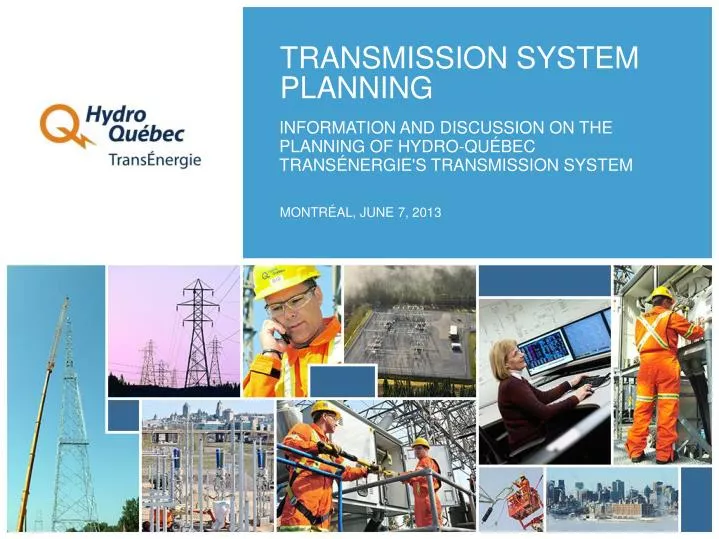
TRANSMISSION SYSTEM PLANNING. INFORMATION AND DISCUSSION ON THE PLANNING OF HYDRO-QUÉBEC TRANSÉNERGIE'S TRANSMISSION SYSTEM. MONTRÉAL, JUNE 7, 2013. HYDRO-QUÉBEC TRANSÉNERGIE. HYDRO-QUÉBEC’S DIVISIONS. HYDRO-QUÉBEC TRANSÉNERGIE WORKFORCE AT DEC. 31, 2012.

E N D
TRANSMISSION SYSTEM PLANNING INFORMATION AND DISCUSSION ON THE PLANNING OF HYDRO-QUÉBEC TRANSÉNERGIE'S TRANSMISSION SYSTEM MONTRÉAL, JUNE 7, 2013
HYDRO-QUÉBEC TRANSÉNERGIE: ROLE AND MISSION Operate the most extensive transmission system inNorth America. "Hydro-Québec TransÉnergie transmits electricity and markets system capacity, while maintaining the necessary standard of reliability." Marketing of transmission services • Transmission Provider • Operation • Maintenance • Planning • System Controller • System reliability • Balancing supply/demand • In charge of exchanges OATT
North American Electric Reliability Corporation (NERC) (Electric Reliability Organization certified by FERC) North American reliability standards MANAGING RELIABILITY IN NORTH AMERICA • Northeast Power Coordinating Council (NPCC)and other regional reliability organizations • Regional reliability standards, coordination, assessment • Balancing Authority Area (Québec, Ontario, New York, New England, Maritimes) (for the NPCC)
NERC (NORTH AMERICAN ELECTRIC RELIABILITY CORPORATION) Major NERC synchronous systems ORGANIZATION CREATED IN 1968 FOLLOWING THE NOVEMBER 9, 1965 BLACKOUT (Electric Reliability Organization certified by FERC) • Made up of eightregionalorganizations • Mandate: promote the reliability of North American power systems • Role: establish basic guidelines for system planning, operation and maintenance www.nerc.com
NPCC (NORTHEAST POWER COORDINATING COUNCIL) ONE OF EIGHT REGIONAL ENTITIES • Mandate: promote reliability of power systems in North-East North America • Role: • Participate in NERC guideline preparation • Establish regional guidelines • Monitor the application and enforcement: • of the entity’s guidelines • of NERC’s guidelines NSPI HQT NBSO IESO ISNE NYIS NPCC Balancing Authority Areas
REGULATION IN NORTH AMERICA • In the United States: FERC jurisdiction • Access to transmission systems • Transmission rates for commercial exchanges between markets • Authority on commercial terms and conditions • Approval of reliability standards • In Canada: provincial jurisdiction • In Québec: the Régie de l’énergie regulates the Transmission Provider
THE RÉGIE DE L’ÉNERGIE (QUÉBEC ENERGY BOARD) MAIN RESPONSIBILITIES RELATED TO POWER TRANSMISSION • Set or amend transmission tariffs and terms of service • Authorize the acquisition, construction or disposal of transmission assets • Approve standards governing operations and technical requirements, including reliability standards • Examine all customer complaints regarding the application of transmission rates
THE TRANSMISSION SYSTEM – TABLE OF CONTENTS Description • Our system • Our interconnections • System features • Specifics Development of major transmission corridors System technologies 1 2 3
ELECTRIC POWER TRANSMISSION ILLUSTRATED 1 HYDRO-QUÉBEC TRANSÉNERGIE'S TRANSMISSION SYSTEM SATELLITE SUBSTATIONS (315 TO 44 kV) G.S. SWITCHYARDS STRATEGIC SUBSTATIONS (735 TO 315 kV) SOURCE SUBSTATIONS (315 TO 69 kV) LINES LINES LINES NEIGHBORING SYSTEMS
TRANSMISSION SYSTEM DESCRIPTION 1 OUR SYSTEM:THE MOST EXTENSIVE IN NORTH AMERICA • 516 substations at different voltages • 33,639 km of lines at different voltages • Assets worth $19.1 billion At December 31, 2012
SYSTEM CHARACTERISTICS:ROBUST MAIN TRANSMISSION BACKBONE 1 ROBUST MAIN TRANSMISSION BACKBONE DEDICATED TO MOVING LARGE AMOUNTS OF POWER • 735-kV Transmission system • 2 major 1,000-km corridors • 38 substations and 11,422 km of lines • Dynamic voltage-support equipment installed throughout the system • Series compensation • ±450-kV DC multi-terminal line Radisson–Nicolet–Sandy Pond (U.S.A.)
SYSTEM CHARACTERISTICS: REMOTE GENERATION AND HIGH WINTER PEAKS 1 MAINLY REMOTEHYDROELECTRIC GENERATION • 85% of generationlocated in the north • 85% of loadlocated in the south HIGH WINTER PEAKS • Winter peakis about 175% of summerpeak • Record hourlypeak of 38,797 MW reached January 23, 2013 BAIE JAMES COMPLEX (16,900 MW) CHURCHILL FALLS COMPLEX(5,200 MW) MANIC-OUTARDESCOMPLEX(9,150 MW)
SYSTEM CHARACTERISTICS:ASYNCHRONOUS WITH THE EASTERN INTERCONNECTION 1 CONSTRAINTS RELATED TO SYSTEM FREQUENCY • Lowerinertiathanother interconnections • Higherfrequency excursions • Unexpectedgeneration or loadlosses must belimited by system design • Frequency must bemanaged • Operating reserve management
SYSTEM CHARACTERISTICS:ASYNCHRONOUS WITH THE EASTERN INTERCONNECTION MAJOR HDVC INTERCONNECTIONS RMCC (2,000 MW) Outaouais (1,250 MW) Châteauguay (1,000 MW) Madawaska (435 MW) CONTROLLABLE HDVC LINKS Control of transfers between systems Elimination of event propagation from one Interconnection to another 1
TRANSMISSION SYSTEM DEVELOPMENT 2 BERSIMIS GENERATING STATIONS (1956-1959) • 315-kV links to Montréal and Québec MANICOUAGAN-OUTARDES AND CHURCHILL FALLS COMPLEXES (1965-1978) • First 735-kV transmission corridor LA GRANDE COMPLEX PHASE I (1979-1986) • New 735-kV line corridors to Montréal and Québec (5 lines) • Loop around Montréal EXPANSION OF LA GRANDE AND MANICOUAGAN COMPLEXES (1987-1996) • Radisson–Nicolet–Sandy Pond direct current line • New 735-kV line in the Baie-James corridor SYSTEM EXPANSION (1997+) • Series compensation on the 735-kV system • New 735-kV line between Hertel and Des Cantons substations
TRANSMISSION SYSTEM TECHNOLOGIES 3 HYDRO-QUÉBEC'S SYSTEM IS COMPLEX, EXTENSIVE AND MAKES USE OF MOST OF THE TECHNOLOGIES AVAILABLE FOR LARGE TRANSMISSION SYSTEMS • Very high-voltage transmission (735 kV) • Direct-current interconnections • Dynamic shunt compensation • Series compensation • Static excitation systems with power stabilizers • Special protection systems THESE TECHNOLOGIES ARE THE MAIN DISTINCTIVE ELEMENTS THAT ENSURE HYDRO-QUÉBEC'S SYSTEM RELIABILITY
A STRATEGIC ROLE 3 Electricity at the heart of the economy Electric heating Consequences of a major outage Montréal, January 23, 2013
PLANNING – TABLE OF CONTENTS Definition General background and observations Evolution of the reliability level and strategic role Major design principles Design criteria Two major system components Four major planning activities Plans Expertise 1 2 3 4 5 6 7 8 9
DEFINITION 1 • Planning • Determine specific objectives • Means to reach them within prescribed deadlines • Organize based on a plan • Therefore, planning at Hydro-Québec means: • Organizing a structured and integrated approach • Taking needs into account • Identifying optimal solutions • Ensuring consistency of development • global, long-term vision of system evolution
INTEGRATED SYSTEM PLANNING (1) 1 • Long-term view • Global vision of challenges, problems and actions to be implemented • Consistency for entire system • Needs based on available and predictable information • Assessment of different scenarios to ultimately determine the optimal scenario
INTEGRATED SYSTEM PLANNING (2) 1 MAIN CONSIDERATIONS • Distributor’s needs for local load • Requests from customers (connections to grid, point-to-point service) • Long-term operability • Technological innovation • Quality improvement • Standards and regulations • System control • Telecommunications 1 2 3 4 5 6 7 8
OBSERVATIONS 2 • The system has distinctive features • Transmission assets make up an integrated whole and their interaction is necessary to the operation and proper functioning of the system • The system must have enough transmission equipment to meet all needs (no planned congestion) • The planning approach must be structured and integrated
EVOLUTION OF THE RELIABILITY LEVEL 3 • The performance requirements initially used to design the system were not as demanding as they are today • The years between 1965 and 1989 were marked by several partial and major outages • Hydro-Québec then invested to improve service continuity and set out to become a full member of the Northeast Power Coordinating Council (NPCC) • Today, Hydro-Québec TransÉnergie boasts a very robust system (no blackout since 1989)
MAJOR SYSTEM DESIGN PRINCIPLES (1) 4 • The context, constraints, observations, evolution in customer needs, etc. have led Hydro-Québec to develop design principles based on reliability • Based on the electrical integrity of the system PRINCIPLE 1 Service continuity must be ensured following the events most likely to occur on the system. PRINCIPLE 2 Measures must be in place to reasonably prevent a blackout after an exceptional event. PRINCIPLE 3 The system’s strategic equipment must not be damaged in the event of a blackout, to ensure that the system can always be restored. • Implementation of special protection systems based on the principle of successive lines of defence
MAJOR SYSTEM DESIGN PRINCIPLES (2) 4 EVENTS INCREASING IN SEVERITY SECOND LINE OF DEFENCE FIRST LINE OF DEFENCE THIRD LINE OF DEFENCE ELECTRICAL INTEGRITY OF THE SYSTEM PRINCIPLE 1 PRINCIPLE 2 PRINCIPLE 3 EVENT FREQUENCY FREQUENT VERY RARE EXCEPTIONAL OBJECTIVES SERVICE CONTINUITY SYSTEM INTEGRITY EQUIPMENT SAFETY MEANS IN PLACE • Intrinsic robustness of the system • Equipment’s major features • Special protection systems • Special operating procedures • Special features of equipment • Special protection systems • Restoration • Blackstart capability • Internal emergency plan RESULTS NO LOSS OF LOAD POSSIBILITY OF PARTIAL OUTAGE WITH QUICK RESTORATION RISK OF BLACKOUT WITH QUICK RESTORATION
MAIN SYSTEM CRITERIA (1) 5 DESIGN CRITERIA IDENTIFY EVENTS FOR WHICH THE SYSTEM MUST MEET AN ACCEPTABLE PERFORMANCE LEVEL BASIC CRITERIA (SYSTEM ROBUSTNESS, NPCC, NERC) • The system must remain stable during and after the most severe of basic events without loss of load and without using special protection systems • Examples of basic events • A three-phase fault on any element and normal trip-out of the element • Simultaneous single-phase faults on each circuit of a double-circuit line • Circuit-breaker fault • Loss of both poles of a direct-current bipolar facility
MAIN SYSTEM CRITERIA (2) 5 COMPLEMENTARY CRITERIA (HQT-SPECIFIC) • The system must remain stable during and after the most severe of the complementary events (some exceptions apply) • Examples of complementary events • Single-phase fault with trip-out of the faulty line and another parallel line • Single-phase fault with trip-out of the line and bypass of series capacitor bank on a parallel line
MAIN SYSTEM CRITERIA (3) 5 EXCEPTIONAL EVENTS (NPCC, NERC REQUIREMENTS) • NPCC and NERC require that these events be studied to assess system performance and identify remedial measures • According to Hydro-Québec TransÉnergie’s criteria, the system must remain stable under certain circumstances • Examples of exceptional events • Total loss of a generating station • Loss of all the lines exiting a substation • Loss of a major load centre
REGIONAL SYSTEM CRITERIA 5 GENERAL PRINCIPLES • Equipment capacity adequate in normal mode (N) and during the unavailability of one piece of equipment (N-1) • Supply continuity during simple events; size and duration of load losses limited during more significant events • New 65 MVA or higher substations are supplied by more than one circuit • Voltage levels are maintained within normal ranges • Equipment capacity is adequate to support the system’s short-circuit levels
TWO MAJOR COMPONENTS OF THE SYSTEM 6 THE MAJOR DESIGN PRINCIPLES ARE APPLIED TO THE SYSTEM’S TWO MAJOR COMPONENTS: • Main transmission system (mainly 735 kV and 315 kV) • Transmission system expansion • New hydroelectric and wind power generation • Reliability preservation, voltage control and compliance to design criteria; long-term operability • Transmission system interconnections • Regional systems • Impact of connecting new wind farms on system topology • Overloaded satellite substations, growth in energy requirements • Transformer capability additions • New regional infrastructure • Interconnections in regional systems
FOUR MAJOR PLANNING ACTIVITIES 7 ESTABLISH DESIGN CRITERIA FOR THE SYSTEM AND TECHNICAL CHARACTERISTICS FOR THE EQUIPMENT DESIGN THE SYSTEM DESIGN EQUIPMENT TAKING TRANSIENTS (LIGHTNING, SWITCHING IMPULSES, ETC.) INTO ACCOUNT DEVELOP PROJECTS BASED ON CUSTOMERS’ NEEDS 1 2 3 4
PLANS 8 STRATEGIC PLAN 2009–2013 The strategic plan defines the company’s major objectives, taking into account the shareholder (Québec government) and senior management’s objectives
HYDRO-QUÉBEC TRANSÉNERGIE’S BUSINESS PLAN 8 1 ENSURE THE QUALITY OF POWER TRANSMISSION SERVICE 1 Ensure long-term operability of facilities through targeted investments STRATEGY 2 Ensure system reliability and availability 2 INCREASE TRANSMISSION SYSTEM CAPACITY TO MEET CUSTOMER NEEDS 1 Invest in response to growing needs STRATEGY 2 Increase interconnection transfer capability 3 FURTHER ENHANCE THE DIVISION’S PERFORMANCE 1 Continue to improve performance 2 Optimize investments in a context of strong growth STRATEGY 3 Base innovation efforts on four promising avenues 4 Maintain expertise and develop employees’ skills
EVOLUTION PLANS 8 REGIONAL EVOLUTION PLANS • Extensive knowledge of the regional systems • Anticipate impact of growth and aging of equipment • Set long-term objectives (voltage levels, main equipment, topology) • Consistency of activities throughout entire system • Regional systems divided into smaller or larger entities according to needs • Feedback on criteria and processes MAIN SYSTEM PLANNING • Long-term plans for main transmission system • Reflection on criteria • Participation in NERC and NPCC PLANNING BY SUBSTATION • Asset sustainment plans
PROCESS FOR CARRYING OUT A PROJECT – CONTENTS Background The four steps of the process Planning studies Draft-design mandate Draft-design study Project 1 2 3 4 5 6
BACKGROUND 1 System planning and design is carried out prior to the project process • The major objectives for the system’s long-term development are determined • Global vision of transmission system issues Transmission-system related projects are initiated in response to: • Customer requests • Needs identified by Hydro-Québec TransÉnergie All projects related to the transmission system follow the same process • Study of different scenarios • Draft-design mandate for the selected scenario • Completion of draft-design study and project
THE FOUR STEPS OF THE PROCESS 2 • PLANNING STUDIES • Identify an optimal solution in response to a customer’s request or to a problem raised • DRAFT-DESIGN MANDATE • Rule on the content of the solution selected in the previous phase • DRAFT-DESIGN STUDY • Set the scope of the project, ensure its acceptability and obtain a commitment for its completion • PROJECT • Implement the solution 44
PLANNING STUDIES 3 • Objective: • Define the needs of the customer • Identify an optimal solution in response to those needs or the problem raised • Includes: • Define needs • Determine the possible impact on the transmission system • Conduct feasibility studies if necessary • Carry out analyses and technical, economic and environmental studies • Recommend optimal solution • According to the Open Access Transmission Tariff, an impact study on the system is carried out when necessary
THE FOUR STEPS OF THE PROCESS 2 • PLANNING STUDIES • Identify an optimal solution in response to a customer's request or to a problem raised • DRAFT-DESIGN MANDATE • Rule on the content of the solution selected in the previous phase • DRAFT-DESIGN STUDY • Set the scope of the project, ensure its acceptability and obtain a commitment for its completion • PROJECT • Implement the solution 46
DRAFT-DESIGN MANDATE 4 • Objective • Rule on the content of the solution selected in the previous phase • Includes: • Prepare specifications for the solution selected • Obtain a draft-design mandate proposal including costs and deadlines • Recommend that a draft-design study be carried out
THE FOUR STEPS OF THE PROCESS 2 • PLANNING STUDIES • Identify an optimal solution in response to a customer's request or to a problem raised • DRAFT-DESIGN MANDATE • Rule on the content of the solution selected in the previous phase • DRAFT-DESIGN STUDY • Set the scope of the project, ensure its acceptability and obtain a commitment for its completion • PROJECT • Implement the solution 48
DRAFT-DESIGN STUDY 5 • Objective: • Set the the scope of the project in terms of costs, content and deadlines • Ensure its acceptability • Obtain a commitment for its completion • Includes: • Mandate Hydro-Québec Équipement to conduct the draft-design study • Conduct follow-up • Communicate project to the public (consultation and/or information) • Environmental authorization requests, if necessary • Obtain approvals required for modifications to specifications • Recommend the implementation of the project
THE FOUR STEPS OF THE PROCESS 2 • PLANNING STUDIES • Identify an optimal solution in response to a customer's request or to a problem raised • DRAFT-DESIGN MANDATE • Rule on the content of the solution selected in the previous phase • DRAFT-DESIGN STUDY • Set the scope of the project, ensure its acceptability and obtain a commitment for its completion • PROJECT • Implement the solution 50