Download
1 / 25
460 likes | 884 Views
Chapter 4 AC to AC Converters. Outline 4.1 AC voltage controllers 4.2 Other AC controllers 4.3 Thyristor cycloconverters 4.4 Matrix converters. 4.1.1 Single-phase AC voltage controller. Resistive load, quantitative analysis RMS value of output voltage RMS value of output current

E N D
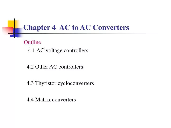
Chapter 4 AC to AC Converters Outline 4.1 AC voltage controllers 4.2 Other AC controllers 4.3 Thyristor cycloconverters 4.4 Matrix converters
Resistive load, quantitative analysis RMS value of output voltage RMS value of output current RMS value of thyristor current Power factor of the circuit
Inductive load, quantitative analysis Differential equation The RMS value of output voltage, output current, and thyristor current can then be calculated.
4.1.2 Three-phase AC voltage controller Classification of three- phase circuits
3- phase 3- wire Y connection AC voltage controller For a time instant, there are 2 possible conduction states: –Each phase has a thyristor conducting. Load voltages are the same as the source voltages. –There are only 2 thyristors conducting, each from a phase. The load voltages of the two conducting phases are half of the corresponding line to line voltage, while the load voltage of the other phase is 0.
4.2 Other AC controllers 4.2.1 Integral cycle control—AC power controller Circuit topologies are the same as AC voltage controllers. Only the control method is different. Load voltage and current are both sinusoidal when thyristors are conducting.
Spectrum of the current inAC power controller There is NO harmonics in the ordinary sense. There is harmonics as to the control frequency. As to the line frequency, these components become fractional harmonics.
4.2.2 Electronic AC switch Circuit topologies are the same as AC voltage controllers. But the back- to- back thyristors are just used like a switch to turn the equipment on or off. Application—Thyristor-switched capacitor (TSC)
TSC waveforms when the capacitor is switched in/out The voltage across the thyristor must be nearly zero when switching in the capacitor, and the current of the thyristor must be zero when switching out the capacitor.
TSC with the electronic switch realized by a thyristor and an anti-parallel diode The capacitor voltage will be always charged up to the peak of source voltage. The response to switching- out command could be a little slower (maximum delay is one line-cycle).
4.2.3 Chopping control—AC chopper • AC chopper Modes of operation
4.3 Thyristor cycloconverters 4.3.1 Single- phase thyristor-cycloconverter • Circuit configuration and operation principle
Single- phase thyristor-cycloconverter Modes of operation
Modulation methods for firing delay angle Calculation method – For the rectifier circuit
4.3.2 Three- phase thyristor-cyclo converter • The configuration with common input line
Input and output characteristics The maximum output frequency and the harmonics in the output voltage are the same as in single-phase circuit. Input power factor is a little higher than single-phase circuit. Harmonics in the input current is a little lower thanthe single- phase circuit due to the cancellation of some harmonics among the 3 phases. To improve the input power factor: –Use DC bias or 3k order component bias on each of the 3 output phase voltages • Features and applications Features: –Direct frequency conversion—high efficiency –Bidirectional energy flow, easy to realize 4- quadrant operation –Very complicated—too many power semiconductor devices –Low output frequency –Low input power factor and bad input current waveform Applications: –High power low speed AC motor drive
4.4 Matrix converter • Circuit configuration
Features Direct frequency conversion—high efficiency can realize good input and output waveforms, low harmonics, and nearly unity displacement factor Bidirectional energy flow, easy to realize 4-quadrant operation Output frequency is not limited by input frequency No need for bulk capacitor (as compared to indirect frequency converter) Very complicated—too many power semiconductor devices Output voltage magnitude is a little lower as compared to indirect frequency converter.