Download

1 / 36
360 likes | 498 Views
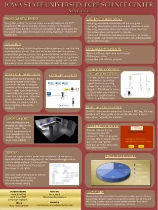
Iowa State Science Center. Client: Iowa State (Thorland-Oster, Vicky) Advisors: Dr. Jacobson, Douglas W Team: Moran, Alex S Kang, June K You, Seung H. Problem Statement. Concept Sketch. System block diagram. System description. Operating environment.

E N D
Iowa State Science Center Client: Iowa State (Thorland-Oster, Vicky) Advisors: Dr. Jacobson, Douglas W Team: Moran, Alex S Kang, June K You, Seung H
Operating environment • All equipment shall be capable of operating without degradation between 10⁰C and 52⁰C • All equipment shall be capable of operating without degradation over a humidity range of 0-60% (standard indoor humidity) • All equipment shall be capable of operating without degradation by means of a standard wall outlet. • All equipment that does not require 120VAC shall be capable of operating with limited risk (cost) involved. • All equipment shall be encased in such a way as to minimize risk of breaking by human interaction. • All equipment shall be protected and wired so that no electric shock risk is present.
Functional requirements • The Sonar Array shall be capable of detecting objects from four different stationary points. • The Sonar Array shall be capable of detecting objects between 3 and 21 feet from the sensor. • The Sonar sensors shall be capable of being interpreted by an analog to digital converter. • The heat sensor shall be capable of operating between 0 and 100 degrees Fahrenheit. • The Heat sensor shall be capable of being interpreted by an analog to digital converter. • Recognition distance shall be operational between 0 and 2 meters. • The RFID shall be capable of recognizing no less than 100 different signals. • The RFID shall be capable of transmitting information via an Ethernet connection to the main computer. • The RFID shall be capable of connection with the computer via RS-232 for RFID software updates.
Functional Requirements (Continued) • The RFID shall be capable of writing tags at a distance of at least 6 inches. • The LED display shall be capable of transitioning between different intensity values. • The LED intensities will be individually dependant on the inputs from the chosen input signal. • The LED display shall have independent control for each light bar. • The monitor shall be able to output RFID identification • The monitor shall be capable of displaying the current thermistor heat value. • The monitor shall be capable of displaying the Bluetooth information • The monitor shall be capable of being read in ambient light. • The Controller shall be capable of switching between at least 3 different devices.
Non-functional requirements • The ISSC shall contain 4 sonar sensors. • The Sonar sensor shall be capable of operation between 3.5 and 5.5 Volts • The ISSC shall contain 2 heat sensors. • The heat sensor shall be capable of outputting between 0 and 5 volts. • The ISSC shall contain 1 RFID reader. • The RFID reader shall operate at a range of 860 MHz to 906 MHz • The RFID shall utilize a built in antenna. • The RFID shall operate off of a 120V power supply • The ISSC shall contain 5 different LED color bars. • The ISSC LEDs shall not be degraded by operation at maximum radiance. • The ISSC LEDs shall operate off of a 12 volt power supply. • The monitor shall be viewable from any point in the room • The monitor shall be color • The monitor shall be able to output RFID identification • The monitor shall be capable of displaying the current thermistor heat value. • The monitor shall be capable of displaying the Bluetooth information • The ISSC shall include a Bluetooth antenna. • The controller will be encased in such a way as to protect from damage.
Deliverables: • Project Evaluation • User Manual • Scripts • Test Results
Issues • Timing limitation with DAQ. • Several Solutions have been attempted, No practical solutions with available hardware given functional requirments • Still waiting for dedicated computer. • PCB has not arrived in time.
Changes Made to the Program • PWM – Linear to discrete Stages • Reason: Limitations of the DAQ-6008 • Sound-LED interaction • Reason: Timing issues between DAQ and sound acquisition. • Sound Output • Reason: Computer limitations. Software exists, however drivers were unable to install due to internet problems with the current computer (untested).
Hardware specification1) ni usb-6008 oem GND AI0 AI4 GND AI1 AI5 GNDAI2 AL6 GND AI3 AI7 GND AO0 AO1 GND GND +5 +2.5V PFIO P1.3 P1.2 P1.1P1.0 P0.7 P0.6 P0.5 P0.4 P0.3 P0.2 P0.1 P0.0 Sonar 1 Heat 1 Sonar 2 Heat 2 Sonar 3 Sonar 4 LED DRIVER 1 LED DRIVER 1 LED DRIVER 1 LED DRIVER 1 LED DRIVER 1
software specification • LabView VI hierarchy shows the software hierarchy for the system.
1) Graphic user interface • The GUI displays the controls for device selection, Manual light control, RFID recognition, Sonar control, Thermistor control, Sound pressure information, and information push buttons with description bar.
2) control • The Control within the GUI selects how the system will be operating.
3) DaC analog signal acquisition DAC SIGNAL ADDITION DAC PWM VALUE
4) SOUND CONTROL • The sound input has a different functionality than the other inputs. OBTAINING A SOUND SAMPLE
5) MANUAL CONTROL • Allows the user to customize the rooms color scheme to their desired preferences.
6) PWM GENERATION • Although the functionality of the PWM changes between the sound input, manual control and the DAC inputs, the logic is identical for all instances.
Testing • Sonar Sensors • Range and functionality are verified. Noise levels are determined for different ranges of each sensor • High Noise: Continuous changes in voltage read • Medium Noise: Takes some time to find distance • Low Noise: Distance is found quickly, with little to no signal distortion. • Led Light Bars • Current and functionality has been verified for each unit. All LED light bars will be operating at 12.5 volts, driving roughly 2.5 to 3 amperes of current when on. Average power is dependant on the duty cycle. • LED Driver • The Driver has been tested using a signal generator for functionality. 5 different test points were chosen, and it was verified that noticeable light control occurred. • Testing is still in progress for integration. Lights are blinking (computer limitations). • Thermistor • Resistivity, and functionality has been verified for both thermistors. Temperatures were checked and verified between the two devices in different ambient temperatures, and with applied heat. • DAQ-6008 • Input functionality has been verified. Resolving output capability. • Sound • Sound input capability has been verified. Sound output is in progress for the RFID. A redesign is necessary for the functionality of the sound to light functionality.
CONCLUSION • While this project was set out to originally be a smaller scope than other projects (due to the small group size), there were definitely some challenges which needed to be overcome in order to successfully complete the Iowa State Science Center, including the need to completely learn several programs from the ground up, with no prior experience. • Despite some small bugs within the system, our group believes that the project was, overall, successful. The only implementation which was not included is expected to be included with the next senior design team, and should be ready for demo by its intended date at Veisha. • This project has been good experience for the future workforce. The information applied in developing the system, from the technical aspects, to the documentation, even the teamwork, will be beneficial in all of our future jobs, no matter where they may be.