Download
1 / 18
180 likes | 541 Views
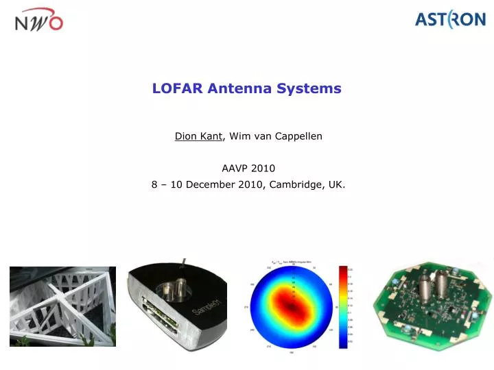
LOFAR Antenna Systems. Dion Kant , Wim van Cappellen AAVP 2010 8 – 10 December 2010, Cambridge, UK. Outline. Requirements and design considerations Low Band Antenna High Band Antenna Summary. Key LOFAR Antenna requirements. Frequency band: 15 – 240 MHz Excluding FM-band 80 – 110 MHz

E N D
LOFAR Antenna Systems Dion Kant, Wim van Cappellen AAVP 2010 8 – 10 December 2010, Cambridge, UK.
Outline • Requirements and design considerations • Low Band Antenna • High Band Antenna • Summary
Key LOFAR Antenna requirements • Frequency band: 15 – 240 MHz • Excluding FM-band 80 – 110 MHz • Sky noise dominated • Large collecting area • Large beamwidth (120 deg) • Height < 2.0 m • Cost effective
LOFAR: 2 antennas • Two antennas: • Low Band Antenna (LBA) 15 – 80 MHz • High Band Antenna (HBA) 110 – 240 MHz • Because: • Completely different sky noise temperatures in low and high bands • One antenna could not meet performance requirements over whole band • Antenna configuration can be different for LBA and HBA: • If one antenna was used, the array would be too dense at 15 MHz or too sparse at 250 MHz. • RFI (FM band) in the middle of LOFAR band
Low Band Antenna • 96 Low Band Antennas per station • Station diameter: 45 – 85 m (LBA) • Sparse pseudo-random configuration
High Band Antenna High Band Antenna • 768 x 2 dipoles per station • Sparse rectangular grid • Analog beamformer per tile (4x4 elements)
LBA and HBA in a nutshell • LOFAR Low Band: 15 – 80 MHz: • Tsky varies from 125,000 to 1,750 K • Array must be very sparse at lowest frequency for high Ae • Per-element digitization • Randomized configuration to smear out grating lobes • Electrically small elements (height <0.1 l at lowest freq) • LOFAR High Band: 120 – 240 MHz • Tsky varies from 600 K to 110 K • Large number of antennas needed for high collecting area • RF beamforming within tile (16 elements), digitization per tile • Regular configuration to reduce costs and ease calibration • Grating lobes suppressed by station rotation
Low Band Antenna • Frequency range: 15 – 80 MHz (l from 20 m to 3.75 m) • Active balun: • Senses open terminal voltage of antenna • Small wrt wavelength to meet environmental requirements • Inefficient radiator at low frequencies, but acceptable due to very high sky noise • But: No RFI filtering possible ahead of active circuits • Low frequency performance set by Tsys • High frequency performance set by pattern degradation
LBA noise performance • Single element simulation and measurement
LBA station system temperature • Estimated Tsys from measured Ae/Tsys of LOFAR station towards zenith and simulated Ae • Simulated Tsys (=Tant + Tsky from previous slide) • Excellent agreement! • Deviation at 80 MHz due to receiver filter (not included in simulation). Simulated Tsys Tsky Estimated Tsys
LBA Station Simulation • Station simulation (96 elements) • Using combined EM and circuit simulation (using in-house CAESAR code) • Results shown at 60 MHz • Used to optimize station configuration • dense vs sparse • Regular vs irregular Aeff Tsys Aeff/Tsys
LBA Temperature dependency • Gain temperature dependency • Measured from -30 to 80 °C • Max. change rate: 0.005 dB / °C (0.1% / °C) • Phase temperature dependency • Max. change rate: 0.06 deg / °C
LBA Environmental tests • Lifetime > 15 years • Suppliers indicate their materials will be OK, but cannot guarantee. • The LBA has been extensively tested: • Ozone, salt-spray and SO2 • Solar radiation (1000 hr) • Tent peg pulling test • Dipole wire pulling test • Liquid penetration test of molded LNA
High Band Antenna • Fat dipole antenna elements in 4x4 tiles • Rectangular array • Element spacing (1.25 m) = l/2 at 120 MHz • True time delays integrated in elements • Beamformer is ‘simple’ combiner • ‘Matched’ LNA • Per tile digitization
HBA Tsys for various scan angles • Simulated Tsys
HBA station estimated Tsys • Tsys estimated from measured Ae/Tsys and simulated Ae. • At this scan angle (7° from zenith) the system is sky noise dominated below 150 MHz.
HBA Station rotation • HBA tiles have a different orientation in every station • The product beam suppresses grating lobes • Individual dipoles are rotated back for calibration purpose x =
Summary • The LOFAR antenna design is highly sky noise dominated: • High sky noise enables electrically small LBA in a very sparse configuration • Lower sky noise in high band forced ‘matched’ LNA’s • But there were many more aspects impacting the design: • RFI • Required array configuration • Performance requirements • Reliabilioty, lifetime • Maintainability • Costs • LOFAR successfully demonstrated a split-band design