Download

1 / 35
350 likes | 743 Views
Novel Multiple-Antenna Systems. Mati Wax. Topics. Location Fingerprinting Beamforming and SDMA for outdoors WLAN. Location Fingerprinting. What is Location Fingerprinting?. A position location technology for rich multipath environments. The key idea:

E N D
Novel Multiple-Antenna Systems Mati Wax
Topics • Location Fingerprinting • Beamforming and SDMA for outdoors WLAN
What is Location Fingerprinting? • A position location technology for rich multipath environments • The key idea: The characteristics of the multipath from a location to the base station antenna-array can serve as a unique identifier – • i.e., as the location “fingerprint”
What is it Good For? • A single-site location technology • All other network-based techniques require multiple sites • Excels where all other position location techniques suffer • Multipath is a major impediment to all position location techniques • GPS, DTOA, TOA, DOA • Outdoors application • Military systems: where GPS is not an option • Commercial systems: complement GPS in urban canyons • Indoors applications • GPS is not applicable indoors • Indoors environments have rich multipath • WLAN systems are widely deployed indoors • WLAN based location fingerprinting is a promising solution
How does it works? Fingerprints Fingerprint 1 Fingerprint 2 ... Fingerprint N-1 Fingerprint N Locations Location 1 Location 2 ... Location N-1 Location N Fingerprints Database Pattern Matching Algorithm Antenna Array Signals Multi-channel Receiver
Fingerprints Data-Base • Created prior to service launch • Raw data obtained by traversing the coverage area and recording the data of every location together with its coordinates • Fingerprints extracted by averaging the data around each grid point • Grid resolution comparable to the achievable accuracy • May need updating if the environment changes
Signal strength as Fingerprint? • Can the Received Signal Strength (RSS) at the base station serve as a good fingerprint? • Absolute signal strength has a poor fingerprint • Depends on the orientation of the handset • Depends on many irrelevant parameters (in/out the car?) • Varies significantly on a wavelength scale due to constructive and destructive multipath interference • Relative signal strength has a better fingerprint • Varies significantly on a wavelength scale due to constructive and destructive multipath interference • Requires multiple sites • Poor accuracy
The Proposed Fingerprints • Spatial fingerprint • The directions-of-arrival (DOAs) of the multipath rays • The relative powers of the multipath rays • Captured by the array covariance matrix • Time-delay fingerprint • The time-delays of the multipath rays • The relative powers of the multipath rays • Captured by the impulse response / power delay profile
How to Compute the Spatial Fingerprint • The Problem: • DOA computation of multipath signals is computationally intensive • The multipath signals are coherent • The solution: • Use the “signal subspace” as the basis for the spatial fingerprint
The Signal Subspace a(θ₁) x(t₁) x(t₂) x(t₃) a(θ₂) x(t)= a(θ₁)s(t-τ₁)+a(θ₂)s(t-τ₂) When moving, the received vectorx(t) stays in the 2-dimensional signal subspace spanned by a(θ₁) and a(θ₂) When stationary, the received vectorx(t) stays in a 1-dimensional subspace
The Likelihood Function LR [i]=Tr[PAiR] where 1 2 N-1 N Tr[ ] is the trace operator R is the received covariance matrix PAi is the projection on the i-th signal subspace Ai corresponding to Ri,the covariance of i-th location
The Pattern Matching Algorithm Pre-compute a set of likelihood functions{LRi} for each Ri, i=1…N,and search for the minimum Euclidean distance to the likelihood function LR obtained from the data • The Euclidean distance allows: • Efficient storage by exploiting norm preserving transformations • Fast search of minima by exploiting the triangular inequality Min| LR- LRi |² {i}
Further Enhancements • Multiple Sites • Will reduce significantly the ambiguity • Will enable good accuracy even in low multipath environments • In pure line-of-sight it degenerates to DOA triangulation • Multiple Frequencies • Will reduce significantly the ambiguity level and improve the accuracy • Mobility • Should be exploited to reduce the ambiguity • The ambiguous locations move randomly, while the true locations follow a smooth track • Time-delay fingerprint • Will reduce significantly the ambiguity and improve the accuracy
Field Test Results • AMPS Phone – Test done by University of Maryland, 2001
References • [1] O. Hilsenrath and M. Wax: “Radio Transmitter Location Finding for Wireless Communication Network Service and Management”, US Patent 6,026,304, Feb 2000. • [2] M. Wax, Y. Meng and O. Hilsenrath: “Subspace signature matching for location ambiguity resolution in wireless communication systems” US Patent 6,064,339, May 2000 • [3] M. Wax, S. Jayaraman and O. Hilsenrath: “Location determination in wireless communication systems using velocity information”, US Patent 6,084,545, July 2000 • [4] S. Jaraman, M. Wax and O. Hilsenrath: “Calibration table generation for wireless location determination”, US Patent 6,101,390, Aug 2000. • [5] M. Wax, S. Jaraman, V. Radionov, G. Lebedev and O. Hilsenrath: “Efficient storage and fast matching of wireless spatial signatures”, US Patent 6,104, 344, Aug 2000. • [6] M. Wax and O. Hilsenrtah: “Signature matching for location determination in wireless communication systems”, US Patent 6,108,557, Aug 2000. • [7] M. Wax and O. Hilsenrath: “Signature matching for location determination in wireless communication systems”, US Patent 6,112,095, Aug 2000. • [8] M. Wax, S. Jaraman and O. Hilsenrath: “Antenna array calibration in wireless communication systems”, US Patent 6,232,918, May 2001. • [9] M. Wax, O. Hilsenrath and A. Bar: “Radio transmitter location finding in CDMA wireless communication systems”, US Patent 6,249,680, June 2001. • [10] M. Wax, A. Bar and O. Hilsenrath: “Measurement of spatial signature information in CDMA wireless communication systems”, US Patent 6,466,565, Oct 2002.
Summary – Location Fingerprinting • A Multiple-antenna single-site position location technology • Excels in rich multipath environments • Outdoors • Indoors • Easily integrated with all next-generation multiple-antenna standards • Cellular, WLAN, WIMAX, LTE • A lot of interesting open problems for research
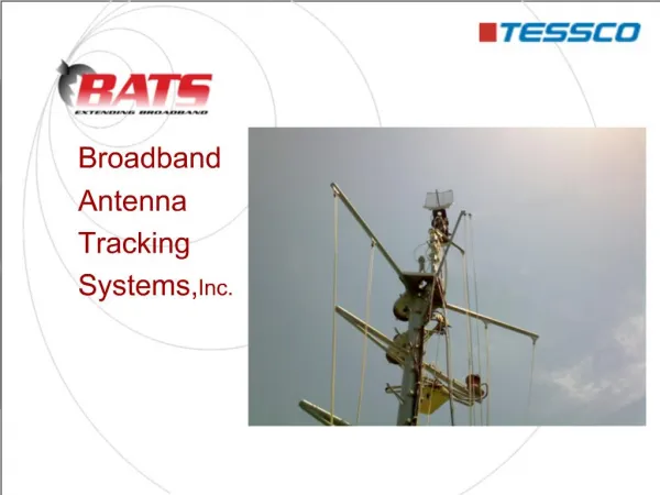
Who needs Outdoors WLANs? • Municipalities / Governments • Education (Digital Inclusion) • Internet to schools and their neighborhood • Municipal applications • Meter reading • Public safety • Video surveillance • Economic development • Business connectivity, tourism • Cellular Carriers / WISPs • The lowest cost broadband wireless alternative • Especially attractive in developing countries • Driven by availability of low-cost embedded clients • Laptops, handsets, PDAs
What Are the Main Challenges? • Cope with interference • Unlicensed band is prone to interference • Level and nature of interference is unpredictable • Provide extended range • Mounting sites are expensive to acquire and maintain • Provide uniform coverage • Minimize dead-spot in coverage • Enable indoors penetration • Penetration lowers deployment costs • Provide high capacity • For bandwidth-hungry applications such as video
The Solution • A 6-antenna base station using • Beamforming • SDMA • Based on custom-designed ASIC • Per packet processing on Rx and Tx • Applicable to all off-the-shelf clients • 802.11b/g
The Base Station Block Diagram Beam Forming & SDMA Standard, Unchanged 802.11 clients RF CPU Wavion ASIC RF RF Wavion ASIC RF RF RF Standard Off-the-shelf RF & Antennas
The ASIC – System on a Chip Analog Front-end Analog Front-end Analog Front-end Wavion ASIC Beamforming Digital Front-end Multi-Antenna Channel Estimation Modem MAC Digital Front-end Weight Calc. DSP Modem PCI Multi Antenna Sync Digital Front-end SDMA • Fully functional WiFi baseband chip • Mixed signal
How is Beamforming Done? • Per-packet weights computation based on channel estimation • Done in the frequency domain per bin • Maximum-ratio combining algorithm • Channel estimation based on packet preamble • Involves a short packet exchange prior to transmission • Continuous on-line calibration of RF-mismatch • Compensating the transmitter/receiver RF-chain mismatch
How is SDMA Done? • Done only in the down link • The random access protocol prevents simultaneous uplink • Requires prior channel estimation to each client • Involves a short packet exchange to each client • The simultaneously transmitted packets are set to the same length by zero padding • Required to prevent uplink transmission during downlink • The corresponding ACKs are transmitted simultaneously after the packet ends • In accordance with the 802.11 protocol • The AP resolves the simultaneously received ACKs • Using the pre-computed weights
Beamforming Gain • Beamforming gain is composed of two parts: • Array gain • Diversity gain • Array gain • On receive: 10*log6 = 6.5 -7.5 dB • On transmit: 20*log6 = 13 -15 dB • Diversity gain (over selection diversity) • 0-6 dB depending on the modulation and multipath severity • Total beamforming gain • On receive: 6.5 – 13.5 dB • On transmit: 13 – 21 dB
FCC “Adaptive Antenna” Rule • For every 3dB antenna gain above 6dBi, the total power output shall be reduced by 1dB below 1W • Implication to Wavion AP: • Antenna gain = 10*log6 + 7.5 = 15 dBi • Total transmitted power = 30 - (15-6)/3 = 27 dBm • 42 dBm directed power to user: (Directed power) = 27 + 10*log6 + 7.5 = 42 dBm 6 dB greater than the 36dBm conventional limit
Self-Backhaul Links • Provide cost effective wireless backhaul • Done in 2.4 GHz using Beamforming at both ends • Provide 20 dB link gain over Selection Diversity (SD) • High throughput • Robust and reliable link
Beamforming Gain - SS 6.5 dB 13.5 dB
Beamforming Gain - OFDM 8 dB 12 dB
Cumberland, US – Comparative Tests • Customer conducted field comparison with conventional AP • Clear advantage both in coverage and in capacity WBS-2400 Conventional AP Area Gain Ratio= 0.13 sq mi/0.035 sq mi = 3.7
Summary – BF & SDMA for WLAN • Enabling technologies for wide-area WLAN deployments • A cost effective solution based on custom-design ASIC • Leverages tight integration with PHY and MAC for optimal performance • Further enhancements: • Spatial “Nulling” of interference • Extending to multiple antenna clients (802.11n)