1 / 19

VLF-band Power Line Channel Sounding

VLF-band Power Line Channel Sounding. David W. Rieken, Zhixi Li, and Chris Fleck Advanced Systems Research & Development Aclara Technologies, LLC St. Louis, MO, USA. Summary. VLF band (1-9 KHz) Not regulated by the FCC Legacy AMI systems (e.g. TWACS, Turtle)

Download Presentation

VLF-band Power Line Channel Sounding

An Image/Link below is provided (as is) to download presentation Download Policy: Content on the Website is provided to you AS IS for your information and personal use and may not be sold / licensed / shared on other websites without getting consent from its author. Content is provided to you AS IS for your information and personal use only. Download presentation by click this link. While downloading, if for some reason you are not able to download a presentation, the publisher may have deleted the file from their server. During download, if you can't get a presentation, the file might be deleted by the publisher.

E N D

Presentation Transcript


  1. VLF-band Power Line Channel Sounding David W. Rieken, Zhixi Li, and Chris Fleck Advanced Systems Research & Development Aclara Technologies, LLC St. Louis, MO, USA

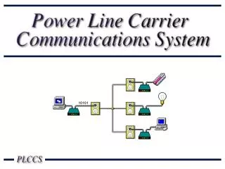
  2. Summary VLF band (1-9 KHz) • Not regulated by the FCC • Legacy AMI systems (e.g. TWACS, Turtle) • Good signal propagation properties? • Signal frequency is higher than mains, but still low enough to permit long distance comms • Presents unique challenges to PLC because of low data rate and significant mains interference Overview • VLF-band channel sounding • Experimental setup • Survey results

  3. Channel sounding algorithm: signal model

  4. Channel sounding algorithm: transmitted signal

  5. Channel sounding algorithm: sounding procedure

  6. Channel sounding algorithm: periodic noise cancelation

  7. Experiment setup

  8. Experiment setup: transmission point

  9. Experiment setup: receive point

  10. Analysis: convolution with sounding signal Spreading signal so that it is orthogonal to mains makes detection in low SNR channels easy.

  11. Survey results: Illinois site

  12. Survey results: Missouri site

  13. SNR Analysis

  14. SNR analysis: Illinois site (7.2 mi link)

  15. SNR analysis: Illinois site (7.2 mi link)

  16. SNR analysis: Missouri site (25.2 mi link)

  17. SNR analysis: Missouri site (25.2 mi link)

  18. Survey results: SNR by band

  19. Conclusions Any VLF-band PLC system must • Accommodate a wide range of link strengths • Leverage higher concentrator data rates than endpoint data rates • Maximize system throughput, rather than instantaneous data rate Analysis shortcomings • Sampling rate offset • Time-varying channel IPR

More Related