Download
1 / 63
630 likes | 671 Views
Chapter 32 Light: Reflection and Refraction. air. air. 1. ConcepTest 32.4a Refraction I. Parallel light rays cross interfaces from air into two different media, 1 and 2 , as shown in the figures below. In which of the media is the light traveling faster ?. 1) medium 1 2) medium 2

E N D
air air 1 ConcepTest 32.4aRefraction I Parallel light rays cross interfaces from air into two different media, 1 and 2, as shown in the figures below. In which of the media is the light traveling faster? 1) medium 1 2) medium 2 3) both the same 2
air air 1 ConcepTest 32.4aRefraction I Parallel light rays cross interfaces from air into two different media, 1 and 2, as shown in the figures below. In which of the media is the light traveling faster? 1) medium 1 2) medium 2 3) both the same The greater the difference in the speed of light between the two media, the greater the bending of the light rays. 2 Follow-up:How does the speed in air compare to that in #1 or #2?
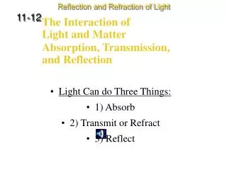
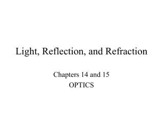
32-6 Visible Spectrum and Dispersion The visible spectrum contains the full range of wavelengths of light that are visible to the human eye.
32-6 Visible Spectrum and Dispersion The index of refraction of many transparent materials, such as glass and water, varies slightly with wavelength. This is how prisms and water droplets create rainbows from sunlight.
32-6 Visible Spectrum and Dispersion This spreading of light into the full spectrum is called dispersion.
32-6 Visible Spectrum and Dispersion Conceptual Example 32-10: Observed color of light under water. We said that color depends on wavelength. For example, for an object emitting 650 nm light in air, we see red. But this is true only in air. If we observe this same object when under water, it still looks red. But the wavelength in water λn is 650 nm/1.33 = 489 nm. Light with wavelength 489 nm would appear blue in air. Can you explain why the light appears red rather than blue when observed under water?
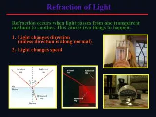
32-7 Total Internal Reflection; Fiber Optics If light passes into a medium with a smaller index of refraction, the angle of refraction is larger. There is an angle of incidence for which the angle of refraction will be 90°; this is called the critical angle:
32-7 Total Internal Reflection; Fiber Optics If the angle of incidence is larger than this, no transmission occurs. This is called total internal reflection.
32-7 Total Internal Reflection; Fiber Optics Conceptual Example 32-11: View up from under water. Describe what a person would see who looked up at the world from beneath the perfectly smooth surface of a lake or swimming pool.
32-7 Total Internal Reflection; Fiber Optics Binoculars often use total internal reflection; this gives true 100% reflection, which even the best mirror cannot do.
32-7 Total Internal Reflection; Fiber Optics Optical fibers also depend on total internal reflection; they are therefore able to transmit light signals with very small losses.
32-8 Refraction at a Spherical Surface Rays from a single point will be focused by a convex spherical interface with a medium of larger index of refraction to a single point, as long as the angles are not too large.
32-8 Refraction at a Spherical Surface Geometry gives the relationship between the indices of refraction, the object distance, the image distance, and the radius of curvature:
32-8 Refraction at a Spherical Surface For a concave spherical interface, the rays will diverge from a virtual image.
32-8 Refraction at a Spherical Surface Example 32-13: A spherical “lens.” A point source of light is placed at a distance of 25.0 cm from the center of a glass (n=1.5) sphere of radius 10.0 cm. Find the image of the source.
Summary of Chapter 32 • Light paths are called rays. • Index of refraction: • Angle of reflection equals angle of incidence. • Plane mirror: image is virtual, upright, and the same size as the object. • Spherical mirror can be concave or convex. • Focal length of the mirror:
Summary of Chapter 32 • Mirror equation: • Magnification: • Real image: light passes through it. • Virtual image: light does not pass through.
Summary of Chapter 32 • Law of refraction (Snell’s law): • Total internal reflection occurs when angle of incidence is greater than critical angle:
Units of Chapter 33 • Thin Lenses; Ray Tracing • The Thin Lens Equation; Magnification • Combinations of Lenses • Lensmaker’s Equation • Cameras: Film and Digital • The Human Eye; Corrective Lenses • Magnifying Glass
Units of Chapter 33 • Telescopes • Compound Microscope • Aberrations of Lenses and Mirrors
33-1 Thin Lenses; Ray Tracing Thin lenses are those whose thickness is small compared to their radius of curvature. They may be either converging (a) or diverging (b).
33-1 Thin Lenses; Ray Tracing Parallel rays are brought to a focus by a converging lens (one that is thicker in the center than it is at the edge).
33-1 Thin Lenses; Ray Tracing A diverging lens (thicker at the edge than in the center) makes parallel light diverge; the focal point is that point where the diverging rays would converge if projected back.
33-1 Thin Lenses; Ray Tracing The power of a lens is the inverse of its focal length: Lens power is measured in diopters, D: 1 D = 1 m-1.
33-1 Thin Lenses; Ray Tracing • Ray tracing for thin lenses is similar to that for mirrors. We have three key rays: • This ray comes in parallel to the axis and exits through the focal point. • This ray comes in through the focal point and exits parallel to the axis. • This ray goes through the center of the lens and is undeflected.
33-1 Thin Lenses; Ray Tracing • Conceptual Example 33-1: Half-blocked lens. • What happens to the image of an object if the top half of a lens is covered by a piece of cardboard? • Top half eliminated • Bottom half eliminated • Image complete; brightness lower
33-1 Thin Lenses; Ray Tracing For a diverging lens, we can use the same three rays; the image is upright and virtual.
33-2 The Thin Lens Equation; Magnification The thin lens equation is similar to the mirror equation:
33-2 The Thin Lens Equation; Magnification • The sign conventions are slightly different: • The focal length is positive for converging lenses and negative for diverging. • The object distance is positive when the object is on the same side as the light entering the lens (not an issue except in compound systems); otherwise it is negative. • The image distance is positive if the image is on the opposite side from the light entering the lens; otherwise it is negative. • The height of the image is positive if the image is upright and negative otherwise.
33-2 The Thin Lens Equation; Magnification The magnification formula is also the same as that for a mirror: The power of a lens is positive if it is converging and negative if it is diverging.
33-2 The Thin Lens Equation; Magnification • Problem Solving: Thin Lenses • Draw a ray diagram. The image is located where the key rays intersect. • Solve for unknowns. • Follow the sign conventions. • Check that your answers are consistent with the ray diagram.
33-2 The Thin Lens Equation; Magnification Example 33-2: Image formed by converging lens. What are (a) the position, and (b) the size, of the image of a 7.6-cm-high leaf placed 1.00 m from a +50.0-mm-focal-length camera lens?
33-2 The Thin Lens Equation; Magnification Example 33-3: Object close to converging lens. An object is placed 10 cm from a 15-cm-focal-length converging lens. Determine the image position and size.
33-2 The Thin Lens Equation; Magnification Example 33-4: Diverging lens. Where must a small insect be placed if a 25-cm-focal-length diverging lens is to form a virtual image 20 cm from the lens, on the same side as the object?
33-3 Combinations of Lenses In lens combinations, the image formed by the first lens becomes the object for the second lens (this is where object distances may be negative). The total magnification is the product of the magnification of each lens.
33-3 Combinations of Lenses Example 33-5: A two-lens system. Two converging lenses, A and B, with focal lengths fA = 20.0 cm and fB = 25.0 cm, are placed 80.0 cm apart. An object is placed 60.0 cm in front of the first lens. Determine (a) the position, and (b) the magnification, of the final image formed by the combination of the two lenses.
33-4 Lensmaker’s Equation This useful equation relates the radii of curvature of the two lens surfaces, and the index of refraction, to the focal length:
33-4 Lensmaker’s Equation Example 33-7: Calculating f for a converging lens. A convex meniscus lens is made from glass with n = 1.50. The radius of curvature of the convex surface is 22.4 cm and that of the concave surface is 46.2 cm. (a) What is the focal length? (b) Where will the image be for an object 2.00 m away?
33-5 Cameras: Film and Digital • Basic parts of a camera: • Lens • Light-tight box • Shutter • Film or electronic sensor
33-5 Cameras: Film and Digital • Camera adjustments: • Shutter speed: controls the amount of time light enters the camera. A faster shutter speed makes a sharper picture. • f-stop: controls the maximum opening of the shutter. This allows the right amount of light to enter to properly expose the film, and must be adjusted for external light conditions. • Focusing: this adjusts the position of the lens so that the image is positioned on the film.
33-5 Cameras: Film and Digital Example 33-8: Camera focus. How far must a 50.0-mm-focal-length camera lens be moved from its infinity setting to sharply focus an object 3.00 m away?
33-6 The Human Eye; Corrective Lenses The human eye resembles a camera in its basic functioning, with an adjustable lens, the iris, and the retina.
33-6 The Human Eye; Corrective Lenses Figure 33-26 goes here. Most of the refraction is done at the surface of the cornea; the lens makes small adjustments to focus at different distances.
33-6 The Human Eye; Corrective Lenses Near point: closest distance at which eye can focus clearly. Normal is about 25 cm. Far point: farthest distance at which object can be seen clearly. Normal is at infinity. Nearsightedness: far point is too close. Farsightedness: near point is too far away.
33-6 The Human Eye; Corrective Lenses Nearsightedness can be corrected with a diverging lens.
33-6 The Human Eye; Corrective Lenses And farsightedness with a diverging lens.