Download
1 / 14
140 likes | 244 Views
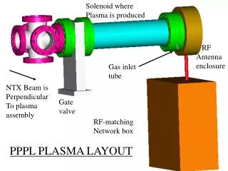
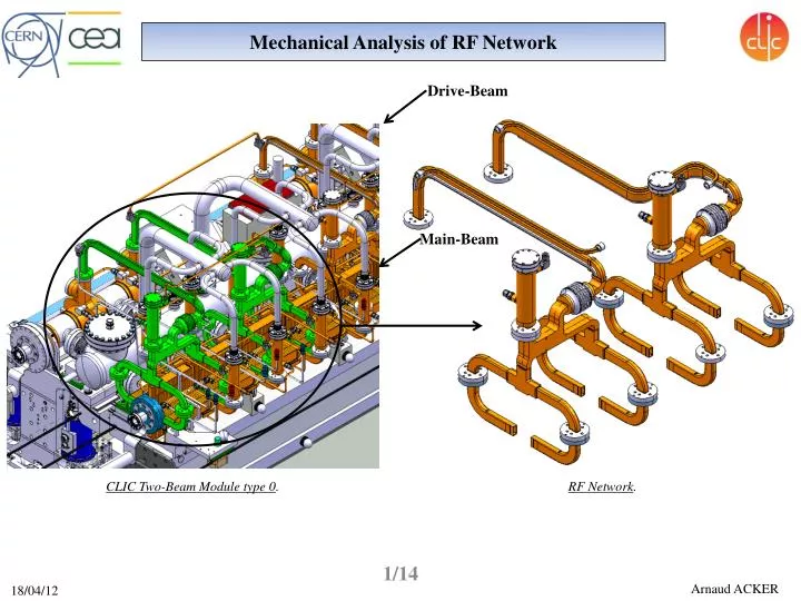
Mechanical Analysis of RF Network. Drive- Beam. CLIC Two- Beam Module type 0. RF Network. Main- Beam. Mechanical Analysis of RF Network. Model ANSYS is consist of :. 2 Waveguides and Cooling Tubes 3 Reinforcements 2 Choke Mode Flanges 2 Hybrids 2 Compact Loads 4 Splitters

E N D
Mechanical Analysis of RF Network Drive-Beam CLIC Two-Beam Module type 0. RF Network. Main-Beam 1/14
Mechanical Analysis of RF Network Model ANSYS is consist of: • 2 Waveguides and Cooling Tubes • 3 Reinforcements • 2 Choke Mode Flanges • 2 Hybrids • 2 Compact Loads • 4 Splitters • 16 Input Waveguides • 26 Flanges → 8 Flanges • 2 Waveguides and Cooling Tubes • 3 Reinforcements • 2 Choke Mode Flanges • 2 Hybrids • 2 Compact Loads • 4 Splitters • 16 Input Waveguides • 26 Flanges Model CATIA is consist of: Waveguide and Cooling Tube Choke Mode Flange Reinforcements Compact Load Hybrid Splitter Input Waveguides 2/14 Model ANSYS Model CATIA
Mechanical Analysis of RF Network Fixed support → Tx = 0, Ty = 0, Tz = 0, Rx = 0, Ry = 0, Rz = 0 (T Translation, R Rotation) 1rst Subassembly Boundary conditions: Fixed supports on Waveguides and Input Waveguides. Fixed supports on the 4 surfaces Fixed supports on the 4 surfaces Fixed supports on the 4 surfaces Fixed supports on the 4 surfaces 2nd Subassembly 3/14
Mechanical Analysis of RF Network Earth Gravity on the RF Network. Vacuum inside of the RF Network. • A force of 340 N both sides of bellows due to vacuum can be divided up as follows: • Application of a pressure of 1 bar (0,1 MPa) on all Waveguide surfaces. • The result of all this is a force of 38,6 Nalong the axis of CMF (Pumping Effect). • Application of a force of 301,4 N on the Bellows Flange corresponding to a pressure of 1 bar on the Choke Mode Flange (taper 1) and the Bellows Flange. Mechanical loads: 1rst and 2nd Subassembly Force of 301,4 N. Waveguide Axis of CMF Bellows Flange Resultant force of 38,6 N along the axis of CMF. Hybrid Pressure of 1 bar on all Waveguide surfaces (Red). CMF(taper 1). 4/14
Mechanical Analysis of RF Network • Application of a pressure of 1 bar (0,1 MPa) on the Hybrid on all its external surfaces. • The result of all this is a force of 64,8 Nalong the axis of the CMF (Pumping Effect). • Application of a force of 275,2 N on the Bellows Flange corresponding to a pressure of 1 bar on the Choke Mode Flange (taper 2) and the Bellows Flange. 1rst and 2nd Subassembly Mechanical loads: Force of 275,2 N. Waveguide Bellows Flange Axis of CMF Resultant force of 64,8 N along the axis of CMF. Hybrid Pressure of 1 bar on all Hybrid external surfaces (Red). CMF(taper 2). 5/14
Mechanical Analysis of RF Network Application of a pressure of 1 bar on all the external surfaces of Splittersand Input Waveguides. 1rst and 2nd Subassembly Mechanical loads: Splitters Hybrid Input Waveguides Pressure of 1 bar on all external surfaces (Red). 6/14
Mechanical Analysis of RF Network Gap of 3 mm before deformation. 1rst Subassembly 2nd Subassembly Results: Contact Contact 7/14
Mechanical Analysis of RF Network 1rst Subassembly Results: Approximately 12 MPa 51 MPa 24,2 MPa 8/14
Mechanical Analysis of RF Network 2nd Subassembly Results: 20 MPa 69 MPa Approximately 7MPa 9/14
Mechanical Analysis of RF Network 2nd Subassembly 1rst Subassembly Waveguide Hybrid Results: Deformation following Y axis Y Y Y Y 10/14
Mechanical Analysis of RF Network 1rst Subassembly 2nd Subassembly Results: Deformation followingX axis X X X X 11/14
Mechanical Analysis of RF Network 1rst Subassembly 2nd Subassembly Z Z Z Z Results: Deformation followingZ axis 12/14
Mechanical Analysis of RF Network Before vacuum Before vacuum Under vacuum Results: Pictures taken at BODYCOTE on 2ndsubassemblywithout reinforcements. Under vacuum Deformed bellows. Result of compression (negative Z axisand positive X axis). Z Y X 13/14
Mechanical Analysis of RF Network • The greatest deformations are found on the Waveguides and CMF region: • The phase error could appear. • Friction forces introduced if 2 tapers of CMF are in contact. • The greatest stresses are found in CMFs and at the feet of Waveguides (around PETS Compact Couplers zone): • CMF → 51 MPa for the 1stCMF and 69 MPa for the 2ndCMF. • WG → 24,2 MPa for the 1stWG and 20 MPa for the 2nd WG. • Reinforcements ribs are not sufficient to provide needed the Waveguides stiffness. • I would recommend to re-design the Reinforcements or find an alternative solution. • Concerning the CMF. • The use of an equivalent cylinder for the simplification of bellows is not a recommended method since the results are not similar to the reality. Conclusion Bellows 14/14