Download

1 / 18
190 likes | 506 Views
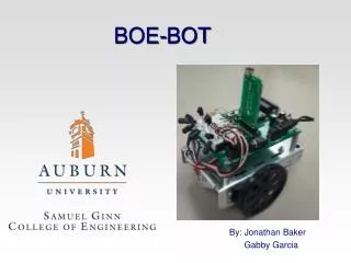
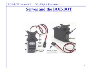
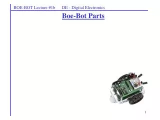
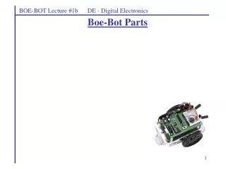
The Boe-Bot and Servo Motors. The Boe-Bot and Servo Motors. This presentation will Present an overview of the Boe-Bot Assemble. Detail how Servo Motors work, and how they are used to control the movement of the Boe-Bot. The Completed Boe-Bot. Assemble : Chassis (1 of 5).

E N D
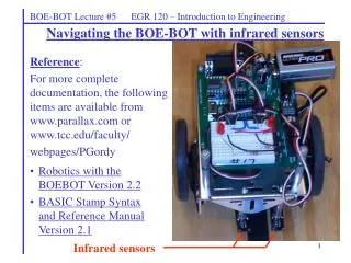
The Boe-Bot and Servo Motors This presentation will • Present an overview of the Boe-Bot Assemble. • Detail how Servo Motors work, and how they are used to control the movement of the Boe-Bot.
Servo Motor Connections Servo Motors are connected to… • P13 – Left Servo • P12 – Right Servo
Vdd / Vin Jumper Setting Jumper • The BOE provides a jumper that allows the Servo Motor to be powered by Vin or Vdd. • If you are using a 9 v battery or a Wall-wart transformer, the jumper should be in the Vdd position. • If you are using a 6 v battery pack, either setting will work. • Since we will be using all three power sources, the jumper should be in the Vdd position.
Servo Motor – Power Position • Power Switch Positions • 0) OFF • STAMP • STAMP and Servo Motor Connectors X4 & X5.
PULSOUT Command PULSOUTPin, Duration • Pin : Specifies the I/O pin (0- 15) to use. • Duration : Specifies the duration (in 2 µs increments) of the pulse. Example: PULSOUT 12, 400 Sends a pulse of 800 µs (400 x 2 µs) to pin 12.
Controlling The Servo Motors DO PULSOUT 12, 750 PAUSE 20 LOOP 750 750 x 2 µs = 1500 µs = 1.5 ms 20 ms
Controlling The Servo Motors DO PULSOUT 12, 750 PAUSE 20 LOOP Motor Still DO PULSOUT 12, 650 PAUSE 20 LOOP Full Speed Clockwise DO PULSOUT 12, 850 PAUSE 20 LOOP Full Speed Counter-Clockwise
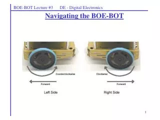
Servo Motor Test Left Motor (13) Right Motor (12) Spin Right Spin Left Reverse Forward
Calculating Motor Time The code below will move the Boe-Bot in reverse. Assuming that the code overhead (i.e. the time it take for the microcontroller to execute the code) is 1.6 ms, verify that the code will cause the Boe-Bot to move in reverse for 3 seconds.
Motor Time Example Calculate the For-Loop-Limit that is required to move the Boe-Bot forward for 4.5 seconds. Again, assume that the code overhead is 1.6 ms.
Resources Parallax Inc. (2004). What’s A Microcontroller. • Retrieved July 15, 2009 • fttp://www.parallax.com/tabid/440/Default.aspx