Download
1 / 10
100 likes | 215 Views
BOE-BOT Lecture #2 EGR 120 – Introduction to Engineering. Servos and the BOE-BOT Reference : For more complete documentation, the following items are available from www.parallax.com or www.tcc.edu/faculty/webpages/PGordy Robotics with the BOEBOT Version 2.2

E N D
BOE-BOT Lecture #2 EGR 120 – Introduction to Engineering • Servos and the BOE-BOT • Reference: • For more complete documentation, the following items are available from www.parallax.com or www.tcc.edu/faculty/webpages/PGordy • Robotics with the BOEBOT Version 2.2 • BASIC Stamp Syntax and Reference Manual Version 2.1
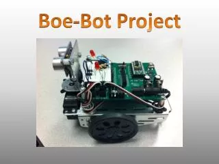
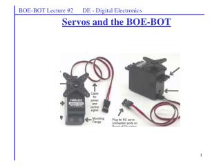
BOE-BOT Lecture #2 EGR 120 – Introduction to Engineering • Servo • A servo is a single device that contains: • Motor • Gearbox that gears down the motor to provide slower speeds (than most motors) and higher torque (power to turn). • Built-in electronics such that the motor position or speed can be controlled by a series of pulses. The servo is powered using 5V (4.8 – 6.0 V)
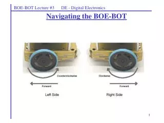
0 degrees 90 degrees 180 degrees 0º 180º 90º Full speed CW Stop Full speed CCW CW Stop CCW BOE-BOT Lecture #2 EGR 120 – Introduction to Engineering • Types of servos • There are two types of servos: • Unmodified servos – the servo can turn over a certain range, such as 180º • This type of servo is commonly used on RC (radio control) cars and airplanes for steering, moving control flaps, etc. • Most servos are of this type • Available in hobby stores, such as Hobbytown USA or Hungates • The servo position is controlled by varying the pulse width of a control signal (see below) • Modified servos • This type of servo has been modified internally so that it will turn continuously. • This type of servo is useful as a drive motor for a robot, such as the BOE-BOT. • The servo speed is controlled by varying the pulse width of a control signal (see below) Pass around servos of each type in class
1 ms 1 ms P6 20 ms BOE-BOT Lecture #2 EGR 120 – Introduction to Engineering Controlling servos with the BASIC Stamp As just seen, servos are controlled by varying the pulse width of a control signal. This is easily done using the PULSOUT command. Recall that this command was also used to turn ON and OFF an LED with the BOE-BOT in an earlier lab. The form of the PULSOUT command is shown below: PULSOUT Command PULSOUT Pin Duration - this command is used to set the specified Pin HIGH for a time equal to Duration multiplied by 2 us. Example: PULSOUT 6, 500 - set P5 HIGH for 1000 us = 1 ms If the example command above was used in the program shown below, it would produce the waveform shown. DO PULSOUT 6, 500 ‘Set P6 HIGH for 1 ms PAUSE 20 ‘Pause for 20 ms LOOP ‘ Loop continuously
BOE-BOT Lecture #2 EGR 120 – Introduction to Engineering Additional PBASIC Commands Variables are defined in PBASIC as follows. VAR Command Name VAR Size where size can be BIT, NIB, BYTE, or WORD where BIT uses 1 binary digit (bit) to store the value (so the max value is 1) NIB uses 4 bits to store the value (so the max value is 11112 = 1510) BYTE uses 8 bits to store the value (so the max value is 111111112 = 25510) WORD uses 16 bits to store the value (so the max value is 11111111111111112 = 6553510) Examples: X VAR BYTE X = 37 Mouse VAR BIT ‘Value can be 0 or 1 Cat VAR NIB ‘Value can be 0 to 15 Dog VAR BYTE ‘Value can be 0 to 255 Rhino VAR WORD ‘Value can be 0 to 65535 Mouse = 1 Cat = 8 Dog = 48 Rhino = 12345
BOE-BOT Lecture #2 EGR 120 – Introduction to Engineering Additional PBASIC Commands Loops can be created in PBASIC in several manners. If a set of instructions are to be performed a specific number of times, the FOR … NEXT loop is convenient. FOR … NEXT Loop Command Count VAR Word ‘Use any variable name to serve as a loop counter FOR Count = InitialValue TO FinalValue STEP Increment List of instructions NEXT Example: (What does this program do?) N VAR BYTE FOR N = 0 TO 50 STEP 2 DEBUG CR,”HELL0” NEXT
BOE-BOT Lecture #2 EGR 120 – Introduction to Engineering Example: (What does this program do if an LED is connected to P12?) Number VAR Word FOR Number = 0 TO 10 ‘The increment equals 1 if STEP is omitted HIGH 12 PAUSE 1000 LOW 12 PAUSE 1000 NEXT What is the difference between the two programs shown below? DO PULSOUT 6, 500 PAUSE 20 LOOP M VAR Word FOR M = 1 TO 100 PULSOUT 6, 500 PAUSE 20 NEXT Estimate how long the second program will run (recall that the BASIC Stamp 2 executes about 4000 instructions/second so each instruction takes about 0.25 ms, not including any delays specified by the instruction).
Stop Full speed CW DO PULSOUT 6, 650 ‘Set P6 HIGH for 1.3 ms PAUSE 20 ‘Pause for 20 ms LOOP ‘ Loop continuously DO PULSOUT 6, 750 ‘Set P6 HIGH for 1.5 ms PAUSE 20 ‘Pause for 20 ms LOOP ‘ Loop continuously Full speed CCW DO PULSOUT 6, 850 ‘Set P6 HIGH for 1.7 ms PAUSE 20 ‘Pause for 20 ms LOOP ‘ Loop continuously 1.3 ms 1.7 ms 1.5 ms 1.3 ms 1.7 ms 1.5 ms P6 P6 P6 20 ms 20 ms 20 ms BOE-BOT Lecture #2 EGR 120 – Introduction to Engineering Servos typically operate by receiving control signals where the pulse width varies from about 1.3us to about 1.7ms. So the signals shown below and the corresponding programs can be used to control a servo.
Example: Right-wheel servo test Each servo is a little different from the next, so in Team Assignment #3, each group will test their two servos by varying the pulse width gradually in order to determine the servos speed and direction for each value of Duration used with the PULSOUT Pin Duration command. Sample Test Program (servo connected to P13) FOR N = 1 T0 1000 PULSOUT 13, 650 PAUSE 20 NEXT Vary the Duration from 650 to 850 and count the wheel revolutions BOE-BOT Lecture #2 EGR 120 – Introduction to Engineering Pick a number large enough so that you will have time to count the wheel revolutions.
BOE-BOT Lecture #2 EGR 120 – Introduction to Engineering Team Assignment #3 In Team Assignment #3 you will record the number of RPM’s for each PULSOUT comment for each servo. You will also graph the information (similar to the graphs shown below). Your data will be used in later labs to determine which PULSOUT commands are needed to make your BOEBOT move around a track.