Download
1 / 23
230 likes | 402 Views
Imperial laser system and analysis. Paul Dauncey, Matt Noy. Laser/stage set up. Matt revived a set of x-y stages and laser/microscope system Unused for several years Interfaced to USB_DAQ board so easy to drive with DAQ Laser specs Wavelength 1064nm Power 50mW Timings

E N D
Imperial laser system and analysis Paul Dauncey, Matt Noy Paul Dauncey
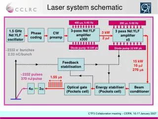
Laser/stage set up • Matt revived a set of x-y stages and laser/microscope system • Unused for several years • Interfaced to USB_DAQ board so easy to drive with DAQ • Laser specs • Wavelength 1064nm • Power 50mW • Timings • Laser fires ~2.5ms after start of bunch train (adjustable but fixed here) • Laser pulse length is 25ns • Number of bunch crossings set to 10 ~ 4.0ms • Laser hit seen in bunch crossing 8 (counting from 0), i.e. ~3.2ms • Note, single pixel cannot fill memory with only 10 bunch crossings • Only got working last Tuesday • All results here are really commissioning-level Paul Dauncey
Alignment • Move to ~10 semi-random positions on sensor • Tried for corners and centre but not all gave a response • Do position scan (like Anne-Marie’s results) • Coarser; 12 steps of 10mm in each direction • 120mm should always fully include at least one pixel • Find average stage position weighted by number of hits per position for each pixel • Try to identify “good”, fully-contained pixels to use • Fit points for each axis direction and scale separately • Axes scales: 0.9962±0.0014, 0.9977±0.0006; ~0.3% difference to sensor • Axes angles: 6.0±0.6mrad, 9.0±1.4mrad; ~3mrad non-orthogonality • Both cases: error ~0.001 means 10mm error over full sensor movement • Position of overall coordinate system ±3.5mm • Relative motion over short distances much better; ~0.1mm Paul Dauncey
Threshold scans • Move to centre of chosen pixel • Within errors of alignment • Anne-Marie’s plots show not so sensitive at 5mm level • Mask all pixels but the chosen one • See plots on next page • Scan threshold, −500TU → 500TU in steps of 5TU • Take 1000 bunch trains at each threshold value • For next few plots, all chosen pixels were shapers • Looked at 3×3 pixels in Quad0 (x<84) and 5×5 pixels in Quad1 (x≥84) • Statistics limited by time to do fits… Paul Dauncey
Effect of laser and masking Laser disabled Others unmasked Laser disabled Others masked Laser enabled Others masked Laser enabled Others unmasked Laser signal falling edge same for both; masked runs much quicker! Paul Dauncey
Different masks Whole sensor Single pixel Whole row Whole column Paul Dauncey
Effect of common mode Common mode = 3200 Common mode = 3072 Common mode = 3456 Common mode = 3328 Common mode = 3584 Off scale completely! Paul Dauncey
Effect of timing Threshold 60TU Paul Dauncey
Effect of timing (cont) Threshold 60TU Threshold 40TU Threshold 100TU Threshold 80TU Paul Dauncey
Effect of timing (cont) Threshold 20TU Apparent drop of efficiency at low threshold; gives rings shown by Anne-Marie Paul Dauncey
Pedestal values • Measured from peak around zero • Renato stated (29/02/08) the pedestal shape in the threshold scan plot should be ideally Gaussian with width = noise • Ideally would do threshold scan without laser for every pixel used • Not yet done so fit lower side of Gaussian • Pedestal ~16TU in this pixel • RMS ~5TU, so 5TU steps too coarse for accurate fit • From Jamie’s measurements (also 29/02/08) we guesstimated 1TU ~ 30eV ~ 8e− so this noise would be ~40e−, close to expected • Dip at ~30TU related to ring shown by Anne-Marie Paul Dauncey
Signal extraction • Take derivative of threshold plot (neighbour bin subtraction) to get laser signal Paul Dauncey
Signal values • Fit to simple Gaussian • Note points are correlated (from derivative calculation) so errors uncertain • Not yet at that level of sophistication; fit to erf would be better but less robust • Signal peak ~91TU in this pixel • With Jamie’s scale, this would be 700e− • RMS ~8TU; again 5TU steps are too coarse • RMS is direct measure of spread • Contribution from laser pulse variation and sensor noise • Gives an upper limit on sensor noise if laser assumed negligible • Noise < 8TU ~ 60e − Paul Dauncey
Fit values entered into spreadsheet Quad0 Quad1 Paul Dauncey
Pedestal distribution Paul Dauncey
Correlation of signal vs pedestal means Paul Dauncey
Gain distribution Paul Dauncey
Correlation of gain vs signal RMS Paul Dauncey
Gain/Signal RMS distribution Paul Dauncey
Correlation of signal vs pedestal RMSs Paul Dauncey
Samplers; effect of laser and masking Laser disabled Others unmasked Laser disabled Others masked Laser enabled Others masked Laser enabled Others unmasked Paul Dauncey
Samplers; signal shape • Try same trick with derivative of threshold plot to get laser signal • Double peak structure; common to most sampler pixels • Not understood by me… Paul Dauncey
Conclusions • Variation of pedestal as observed previously • Much smaller variation of gain • Small difference in gain of Quad0 and Quad1 shapers but S/N is roughly the same • Masking makes a big difference to observed pedestal • Noise is < 8TU and may be ~6TU • Samplers not understood… • Many things to do: • More statistics • Set overall calibration scale • Gain independent of trim? • Noise with finer threshold scan, without laser • Cause of masking and noise rate coupling? Paul Dauncey