Download
1 / 18
180 likes | 261 Views
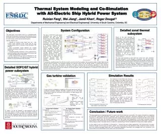
Coupled Thermo-electric VTB Simulation Model of Cooling Loop of a Ship System. ESRDC Modeling and Simulation Workshop Tallahassee, FL 14 February, 2006. Jamil Khan, Ruixian Fang, A. Monti, Wei Jiang, University of South Carolina Greg Anderson, Mark Zerby, Phil Bernatos NSWC, Philadelphia.

E N D
Coupled Thermo-electric VTB Simulation Model of Cooling Loop of a Ship System ESRDC Modeling and Simulation WorkshopTallahassee, FL14 February, 2006 Jamil Khan, Ruixian Fang, A. Monti, Wei Jiang, University of South Carolina Greg Anderson, Mark Zerby, Phil Bernatos NSWC, Philadelphia
Outline • Problem Statement • Models • Thermal • Electrical • Simulation Results • Conclusions
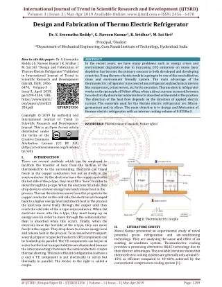
FreshWater Heatsink HeatExchanger Temperature mass flow Level 4 2nd layer of Fw_HEX Level 3 PCM board Level 2 Valve Pipe Mixing model HeatSink Level 1 Pump FreshWater SeaWater HeatExchanger SeaWater Schematic for zone 2
Fresh Water- Sea Water Heat Exchanger • Number of elements can be changed • Governing Eqns for each element: Where ----Fresh water inlet temperature ----Fresh water temperature at time (t-h) ----Average fresh water mixing temperature at time (t-h) ----Mass flow rate ----time step ----Mass in control volume of each element L Fresh water Where ----Fresh water temperature at time t ----Sea water temperature at time t Sea water Tin L/120 Conditions: m*h<=M where M is the mass of fluid of each element, as a special case, e.g., m*h=M , for each time step water in one element totally move into the next element. Sea_Water Element #i
Heat Sink • Assume no temperature gradient along the length direction; • Governing Eqns : T2,Q2 Qa Where ----Inlet heat flow from heat source ---- Outlet heat flow from heatsink ---- heat absorbed by heatsink T1,Q1 Where ----Mass of heatsink ---- Heatsink heat capacity We can also build this modal for several parts if necessary, that will take consider of the temperature difference along the length direction.
FreshWater- HeatSink Heat Exchanger • Each model includes 12 elements; • Governing Eqns for each element: • The same logic used in this model as shown in Fresh water- Sea water HeatExchanger m ,p m ,p Tout Tin Q,T Where ----heatsink temperature at time t ---- heatsink temperature at time t-h m1,p1 m2,p2 #1 #2 #3 T1,final Tin Tav Conditions: m*h<=M where M is the mass of each element, as a special case, e.g., m*h=M , for each time step water in one element totally move into the next element. Q1 Q2 Q3 Q,T from heat sink Element model
Other models T1 m1 • Water Mixing Chamber Model • Valid for 2 entering streams with different mass flow rate and temperature; • Governing Eqns : m2 T2 Which can be written as T_out m_out • Pipe Model • Mainly account for the pressure change caused by height elevation; • Linear Valve Model • Assume pressure drop linearly depends on the throttle opening.
Electrical System Model • models can be seamlessly substitute to perform analysis Two different levels of details have been developed for the Electro-thermal model • Those two with more or less focus on electrical system waveform
Model 1 • The electrical system is represented as a constant power load (the user can specify active and reactive power) • The interaction with the thermal system is given by the efficient coefficient • Any loss resulting from the efficiency calculation is supposed to be a forcing function for the thermal system
Model 1 Three-phase electrical terminal Thermal port
Model 2 • The model includes the power electronics, the control and the electrical machine • The power electronics is modeled through an averaged model • Switching and conduction losses are estimated from the averaged model
Model 2 Induction machine Control system PEBB’s with Thermal port Controlled rectifier
Example simulation results for PCM and Heatsink Model 4 PCM Heat Source 4 Heatsink Temperature
Example simulation results for the freshwater-Seawater HeatExchanger Fresh water inlet Temp. Sea water outlet Temp. Fresh water outlet Temp.
Example simulation results for the freshwater-Seawater HeatExchanger Fresh water Temperature Field #10 Element Length direction #120 Element #110 Element #100 Element #20 Element
Example simulation results for the freshwater-Seawater HeatExchanger #10 Fresh water Temperature #20 Fresh water Temperature #100 Fresh water Temperature #110 Fresh water Temperature #120 Fresh water Temperature
Conclusions • A real time coupled thermo-electrical simulation for slice 2 of DDG-51 has been successfully developed in VTB • The simulation couples electrical and thermal models • Results have been validated with experimental data • The simulations can be extended to include chillers • Transient responses to changing loads can be studied • Simulation is available for demonstration