Download

1 / 42
420 likes | 427 Views
CMS Experiment. CMS Hadron Calorimeter - Arie Bodek University of Rochester DoE Review (15 min Talk) - Wednesday, July 23, 2003 I will only talk about Rochester contributions We==Rochester CDF Plug Upgrade/CMS-HCAL Task D Group) Brief History - Rochester CDF-Plug Upgrade Group

E N D
CMS Experiment • CMS Hadron Calorimeter - Arie Bodek • University of Rochester • DoE Review (15 min Talk) - Wednesday, July 23, 2003 • I will only talk about Rochester contributions • We==Rochester CDF Plug Upgrade/CMS-HCAL Task D Group) • Brief History - Rochester CDF-Plug Upgrade Group • We invented Megatile-Tile-Fiber Technology for CDF • We built the CDF-Plug HCAL • We tested and calibrated CDF-Plug Upgrade Calorimeter in test beam • We developed very large Megatile technology for CMS-Barrel HCAL • We are building all the HCAL Megatiles. Optical Cables, Optical Decoders/Photodetector Boxes for CMS -HCAL • We installed all the Megatiles into CMS-HCAL at CERN • We have have built an ECAL module for the CERN test beam • Rochester (Slattery-Lobkowicz-Ginther) built the massive test beam table • We have led and are leading test beam efforts and analyses at CERN • We are now in charge of all of US-CMS installation at CERN
Outline • Overview • CMS-HCAL Rochester Group • Past CMS HCAL Activities at U of R • Test Beam Motion Table (Slattery/Ginther) • 1995 and 1996 HCAL Test Beam at CERN (data taking, analysis, NIM article) • Design of the HCAL Optics System • Construction of Scintillator Megatiles for Hadron Barrel Calorimeter • Rochester L3 Management Responsibilities, Fermilab FY98-F03 • Present CMS HCAL Activities • HCAL Installation and Commissioning, CERN FY03-07 • TestBeam Activities, 2002,2003, 2004 • Summary
Rochester CMS HCAL Group • Physicists ( at Rochester, FNAL, CERN) • Prof. Arie Bodek (25% CMS, 25% Neutrino, 50% CDF) - current effort • Prof. Paul Slattery (mostly Dzero now) • Pawel de Barbaro (Senior RA) - At CERN - 90% CMS (rest CDF) • Howard Budd (Senior RA) - At FNAL - 30% CMS (rest CDF, Neutrino) • George Ginther (Senior RA) - At FNAL - 5% CMS (rest Dzero) • Willis Sakumoto (Senior RA) - At FNAL - 5% CMS (rest CDF) • Y, S. Chung (RA) - at FNAL - 5% CMS (rest CDF) • Technical Staff (we had 6 techs, now down to 4) • Dan Ruggiero (lab engineer) - 100% CMS Project Funds (At FNAL) • Janina Gielata (technician) - 100% CMS Project Funds (At FNAL)->TOB • Agnieszka Sanocka (technician) -100% CMS Projectd Funds (At FNAL)->TOB • Heng Bao Zeng (technician) - 100% CMS Project Funds (AT FNAL) • Tom Haelen (Engineer) - At Rochester • Summer Students • Matthias Imboden (Bern U., 2002-US citizen NSF-REU) - at CERN summer • Pawel Sopicki (Jagellonian U., 2003) - at CERN summer • Administrative Staff • Sue Brightman and Judy Mack
Installing Megatiles at CERN Rochester CDF Plug Group was in charge of CMS HCAL megatile construction at Fermilab and installation at CERN. Rochester technical staff flew to CERN. Megatile design made this a rather simple job.
H2 Testbeam - Motion Table built by Rochester Dzero Group Built by Slattery, Lobkowicz, Ginther and Engineer Tom Haelen HO HB HE
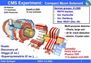
US responsibilities in HCAL • Rochester is responsible for all of HB optics. US responsible for all readout electronics • US is also responsible for readout electronics for HE and HO subdetectors HO 2.2 HB 2.1 HF 2.5 HE 2.3
Design of Optical System • Scintillation light is collected by wavelength shifting (WLS) fibers embedded in the tiles • Outside the tile, WLS fibers are spliced to clear fibers • Clear optical fiber cables with mass terminated connectors carry light to the outside of the detector ----> UNIT IS A MEGATILE read by Optical Cables with Connectors • Decoder boxes re-group fibers from layer-wise to tower-wise scheme and house photodetectors • CMS HCAL HB, HE and HO have adopted most of design features of the CDF End Plug Upgrade
Techical issues specific to CMS • Calorimeter Performance in 4 Tesla Magnetic field • magnetic field has two-fold effect on the response of the • calorimeter. First it changes light yield of the scintillator • and secondly, it affects the particle shower development. • The second effect depends on the field orientation. • HCAL resolution with and w/o crystal ECAL • presence of highly non-compensating lead tungstate crystal electromagnetic calorimeter (ECAL) degrades the overall response of the combined ECAL+HCAL calorimeter to hadrons. • Radiation damage of clear and WLS fibers • assuming int. luminosity of 5x10**5 pb-1 for first ten years • of LHC operations, radiation dose will reach 30 kRads for HB (eta=1.1). Radiation dose scales with 1/theta**3, so that • high eta region (eta ~2.8, HE) is affected most (2.4 Mrads).
Rochester Management Responsibilities • P. de Barbaro was L3 manager responsible for HCAL Optics • Rochester managed the production of megatiles for Hadron Barrel Calorimeter: • Purchasing of materials (over $2M) • Organization of production (14 technicians, 3 years) • Quality control (light yield, uniformity) • L3 manager responsibilities included supervision of several institutes working on the HCAL Optics • Production of scintillator megatiles and optical cables has been completed on time • All HB scintillators have been installed into the absorber in 2002
HCAL Calibration • Goal: Calibrate from test beam to 3%. • Time in HCAL electronics. • Monitor performance, including radiation damage. • Tools: 1.Nitrogen laser distributed to each sub-detector. Excites scintillator • 2.Laser injects light to photo-detectors. • 3.LEDs (fast) inject light to photodetector. Programmable pulser. • 4.Moving wire radioactive source for long term calibration. • 5.Charge injection to ADC’s (QIE). • Specialized calibration modules designed and built to achieve goals.
HCAL Test Beam activities • HCAL had a major test beam effort in 1995 and 1996 • The focus of these test beams were to resolve some technical issues prior to completing the design of optics • UR played a major role in these test beams: • Lobkowicz/Slattery/Ginther/Haelen have designed and constructed HCAL Motion table, able to carry over 100t of detectors • P. de Barbaro was the corresponding author of NIM article sumarizing these test beam results - analysis done by Rochester
Source / Beam Data m- e- RMS 3% RMS 2% We verified wire source calibration works (with muons and electrons) use to get absolute calibration to 2 – 3 %
TB 2002 versus GEANT4 Resolution Linearity Shape difference: e/h (e.m. & nuclear x-sec), leakage……? suppressed zero The agreement is excellent in all the energy range Data systematic error analysis in progress Validate GEANT4 physics models
Test Beam in 2003 • Present test beam runs focus on verification of electronics: • We are testing two 20deg HB wedges, 20 deg of HE module, and 30deg of HO • 40 MHz Charge Integrators (QIE) send data to HCAL Trigger Cards (HTR) via 1.6 GHz link • For each channel, we collect 20 time slices, each time slice is 25ns wide • In addition, we have ECAL module (100 PbWO4 crystals with PMT readout, module designed/built/tested by UR) to study response of the combined ECAL+HCAL, especially in the 53deg crack region.
Rochester Responsibilities at CERN • P. de Barbaro has assumed responsibilities of Installation and Commissioning Coordinator for HCAL at CERN • Rochester responsibilities cover installation of scintillators, optical cables, radioactive source tubes, readout electronics, cooling. • Testing of entire chain (scintillator, photodetector, QIE, DAQ) – vertical slice test
Rochester CMS HCAL task summary • Rochester lead the design, management and production of the optics system for the HCAL Barrel and corresponding test beam activities, • Production of scintillator megatiles and optical cables has been completed. Several test beam runs completed - First NIM article published • Rochester is now responsible for installation and commissioning of HCAL detector at CERN • Rochester Major Tasks in 2003-2004: • installation of HB, HE and HO scintillators, optical cables and readout electronics at CERN • Test and integration of full HCAL readout and DAQ with other sub-detectors (vertical slice test) at CERN • At Fermilab, continue construction of Optical Decoder Boxes and Electronics. • Provide Root Support and Test Beam Analysis - CMS supplemental request for a postdoc to be at CERN.
Back-up transparencies • Additional transparancies - backup for • Short 15 min talk.
Optical Design for Calorimeters Common Technology for HB, HE, HO
Optics-Megatiles Components are the machined scintillator plates, cover plates, fiber assembly (WLS spliced to clear fiber, optical connector) pigtails
Optics-Megatiles • Cross section view of a megatile
HCAL : HB Calorimeter (Barrel) Sampling calorimeter: brass (passive) & scintillator (active) Coverage: |h|<1.3 Depth: 5.8 lint (at h=0)segmentation: f x h = p resolution: ~ 120 %/ 0.087x0.087 17 layers longitudinally, f x h = 4 x 16 towers Completed & assembled 20o f
HCAL : HE Calorimeter (Endcap) Sampling calorimeter: brass (passive) & scintillator (active) Coverage: 1.3<|h|<3 Depth: 10 lint segmentation: f x h = p resolution: ~ 120%/ 0.087x0.087 19 layers longitudinally 20o Completed, assembled, HE-1 installed
HCAL : HO Calorimeter (Outer) Total number of lint till the last sampling layer of HB is < 8 HO: 2 scint. layers around first m layer (extend to~11 lint ) Test Beam 2002 ~ 5% of a 300 GeV p energy is leaked outside the HB HO improves p resolution by ~10% at 300 GeV & linearity Ring 0 Ring 2 Ring 1
19 x 5.5mm HPD Diode Layout Hybrid PhotoDiode photon transducer for HB, HE, HO. Fiberoptic front window, conventional photocathode, pixelated diode (19 channels/device). From DEP, Holland. Need ~ 500 total.
Fiber-Optic Window Photocathode e Ceramic feedthrough PIN Diode array Gain 4000 0 0 16 kV 8 4 HPD
HCAL SOURCE CALIBRATION 2 HB wedges showing plastic tubes temporarily attached to accommodate wire source system. Moving wire radioactive source. Source on tip of ~10 meter wire. Can be sent into each megatile.
beam ADC counts 100 GeV electron h f HCAL – TB2002 beam 300 GeV pion ADC counts h f beam Testbeam setup 16 X 8 towers in Eta - phi 225 GeV muon h f
Single Event in HCAL beam tower phi s = 12% Performance with ECAL
Timing Issues (2003) • Clock and Control Module (CCM) controls relative timing of integration of pulses wrt trigger (LHC clock) • Since HB wedges are over 5m long, signal arrival to QIE could vary by up to 15ns (as a function of detector tower eta) • We used laser pulses to adjust timing for various eta towers, then tested timing with pion beam. • This is important, since for triggering purposes we want to use only 2 time slices. • We have also checked relative timing of the two wedges. • More test beam data will be taken in August 2003, test beam also planned for 2004.
Measuring relative phase of different towers Laser calib system designed to mimic beam timing. It works. Laser and pion measurements track. Can use laser system to measure relative phases of different towers and then program CCA to compensate. TIME Eta Tower number
Relative Phase after alignment Use laser to calculate d(t) offset. Program CCAs. Use electron beam to check. Can easily synchronize to <2ns using laser system
Setting timing of both wedges simultaneously Use “universal” phase constants to set both wedges. Conclude : Rms(w1 or w1) ~ 1.2ns d(w1-w2) <0.2ns Wedges are identical. Can use laser to predict overall timing at CMS up to a constant Wedge 1 Wedge 2 N towers ( Tower phase - mean ) (ns)
Interesting Observation Medium sharing Low Sharing Note apparent phase shift of data (average time of pulse) as function of energy deposition in tower. Electronics group at FNAL is presently working on solution of this problem. Medium sharing Low Sharing Low Sharing
Pileup Studies Trigger on events with a particle in the subsequent bucket as well.
Wedge Modified wedge attachment
Wedge Wedge side view showing skin on surface Cutout for Services Z R