Download
1 / 7
70 likes | 82 Views
Digital Temperature Gauge. System Overview. Software Design. Project Proposal ECE 4330 Patricia Kaminski. Hardware Design. Testing. Instructions: Delete sample document icon and replace with working document icons as follows: Create document in Word. Return to PowerPoint.

E N D
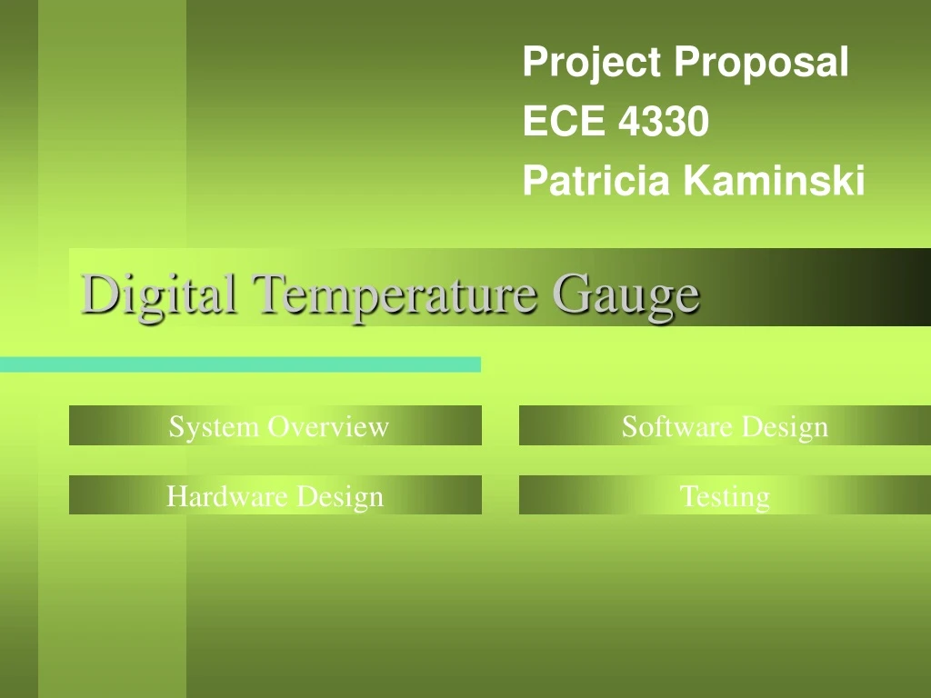
Digital Temperature Gauge System Overview Software Design Project Proposal ECE 4330 Patricia Kaminski Hardware Design Testing
Instructions: • Delete sample document icon and replace with working document icons as follows: • Create document in Word. • Return to PowerPoint. • From Insert Menu, select Object… • Click “Create from File” • Locate File name in “File” box • Make sure “Display as Icon” is checked. • Click OK • Select icon • From Slide Show Menu, Select Action Settings. • Click “Object Action” and select “Edit” • Click OK System Overview • System senses temperature and reports back to the user through the terminal. • It demonstrates the programming and use of a complex external device with the Atmel AVR (Dallas DS1821 Programmable Digital Thermostat and Thermometer). • Added an extra feature to the original design, a cooling system to actively drop the temperature of an overheated part.
Instructions: • Delete sample document icon and replace with working document icons as follows: • Create document in Word. • Return to PowerPoint. • From Insert Menu, select Object… • Click “Create from File” • Locate File name in “File” box • Make sure “Display as Icon” is checked. • Click OK • Select icon • From Slide Show Menu, Select Action Settings. • Click “Object Action” and select “Edit” • Click OK Hardware Design • Uses the Dallas DS1821 Digital Thermometer connected to PA1. • Temperature reporting by RS232 to terminal. • Extended design added a cooling fan connected in the same manner as Lab 6/7/8 that turns on at 25C and increases in speed with increasing temperature.
Instructions: • Delete sample document icon and replace with working document icons as follows: • Create document in Word. • Return to PowerPoint. • From Insert Menu, select Object… • Click “Create from File” • Locate File name in “File” box • Make sure “Display as Icon” is checked. • Click OK • Select icon • From Slide Show Menu, Select Action Settings. • Click “Object Action” and select “Edit” • Click OK Hardware Design • The programmable thermometer is a highly master-slave device (AVR is master). Every access of the thermometer requires a starting signal, even for every bit sent/received. • Every command first requires an initialization (reset) of pulling the data line low for 480us, the direction of the port is then set to input (allowing the pull-up resistor to pull the data line high). 15-60us later the DS1821 pulls the data line low for 60-240us, signaling that the DS1821 is ready for a command. • Each command is 8 bits, with each bit written with a 60us time slot. “One” values are written by pulling the line low for up to 15us and then releasing the line (changing the port to input) for the rest of the 60us. “Zero” values are written by pulling the line low for the full 60us.
Instructions: • Delete sample document icon and replace with working document icons as follows: • Create document in Word. • Return to PowerPoint. • From Insert Menu, select Object… • Click “Create from File” • Locate File name in “File” box • Make sure “Display as Icon” is checked. • Click OK • Select icon • From Slide Show Menu, Select Action Settings. • Click “Object Action” and select “Edit” • Click OK Hardware Design • Commands that return data (8 bits) require the line to be set low for 1us and then the line is released. During the 15us after forcing the data line low and then released, the DS1821 will then force the line either low or high to send the bit. • Difficulties: • Because of the difficulty of verifying correct operation, all timing values had to be verified by oscilloscope. • The documentation did not specify the direction of bits being sent/received. Experimenting showed they are sent/received in a low to high order. • A surface mount chip was accidentally sent, requiring the soldering of wires to connect it to the board.
Instructions: • Delete sample document icon and replace with working document icons as follows: • Create document in Word. • Return to PowerPoint. • From Insert Menu, select Object… • Click “Create from File” • Locate File name in “File” box • Make sure “Display as Icon” is checked. • Click OK • Select icon • From Slide Show Menu, Select Action Settings. • Click “Object Action” and select “Edit” • Click OK Software Design • Each temperature read (and actions) from the DS1821 requires this instruction sequence: • Initialization (Reset) • Start Convert Command (0xEE) • Initialization (Reset) • Read Temperature Command (0xAA) • Reading the data bits from the DS1821 • Adjusting the PWM value (OCR2) to turn on or speed up the fan (depending on temperature) • Outputting the Centigrade and the calculated Fahrenheit values to the terminal
Instructions: • Delete sample document icon and replace with working document icons as follows: • Create document in Word. • Return to PowerPoint. • From Insert Menu, select Object… • Click “Create from File” • Locate File name in “File” box • Make sure “Display as Icon” is checked. • Click OK • Select icon • From Slide Show Menu, Select Action Settings. • Click “Object Action” and select “Edit” • Click OK Testing • Testing was accomplished by comparing reported values from the terminal to an external thermometer. • Temperature changes were made by a hair dryer and an ice pack. • Results: Successful temperature readings and fan operation to cool the chip. Steady state temp was room temp, 22C. Using hair dryer caused reported temp to rise to 62C. Fan operation brought the temp back down to room temp quickly. The ice pack caused temp to drop to 13C. After removal of the pack, temp was sensed at room temp again.