Download
1 / 23
230 likes | 237 Views
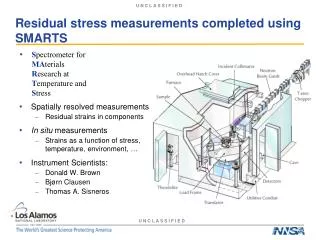
Residual stress tensor distribution monitoring in welds of steels obtained by magnetic techniques. by Athanassios Mamalis and Evangelos V Hristoforou National Technical University of Athens. State of the art in stress monitoring (strain gauges, hole drill…). Material failure

E N D
Residual stress tensor distribution monitoring in welds of steels obtained by magnetic techniques by Athanassios Mamalis and Evangelos V Hristoforou National Technical University of Athens
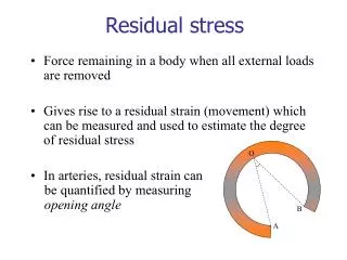
State of the art in stress monitoring(strain gauges, hole drill…)
Material failure • Crack propagation • Micro-cracks • Nano-cracks • Stresses type II & III tensor distribution • Determined by Diffraction • (XRD-BB, EBSD, Neutrons) • Applied NDT methods • Ultrasonic • X-rays • Eddy currents • Magnetic flux leakage • .......... • Magnetic properties • Magnetization loops • Barkhausen noise • Magnetoacoustic emission • Surface permeability • --------- Magnetic Non Destructive Testing Principles & Vision Classic NDT techniques Our method
dM/dt=m(t) E M Magnetic Non-Destructive Evaluation: the innovation Time Time Length Stress field actsas obstacle in domain wall movement during magnetization procedure This is the origin of the magnetic Barkhausen noise (BHN) This is also reflected into the magnetic hysteresis loop Similarly, magnetic acoustic emission illustrates local stresses Surface permeability indicates the surface stresses Domain wall is a self-embedded nano-sensor offering dislocation forest measurement
MatLab or LabView platform for measurements Hysteresis Loop A simplified sensor Field hysteresis loop measurments Parameters: frequency of excitation, amplitude of excitation field, Demagnetization process Magnetic parameters under determination: Coercive field Remanence Saturation field Saturation magnetization Maximum permeability Power losses Initial (virgin) curve Field measurements illustrate sensitive response
2 2 1 1 4 3 3 6 5 5 Surface permeability sensor developed by our group 1: MDL, 2: pulsed current conductors, 3: search coil Device under permanent magnet biasing field (1) MDL, (2) Pulsed current conductors, (3) Search coil, (4) Magnetic surface under test, (5) Permanent magnets, (6) Soft magnetic material for magnetic circuit closure.
2 1 4 3 6 5 5 Device using electromagnet for biasing reasons Surface permeability vs field (1) MDL, (2) Pulsed current conductors, (3) Search coil, (4) Magnetic surface under test, (5) & (6) Soft ferromagnets and excitation coil respectively, to form the biasing electromagnet.
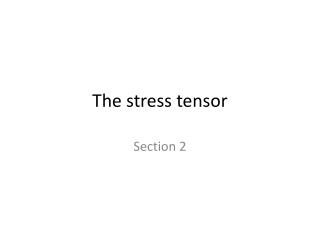
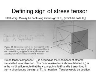
Stresses in steels Stress type I, II & III Uniform stresses (I & II) The reality: stresses type III Topology of lattice parameters offers strain an stress analysis We look for s11 & s22 stress components
Stress determination using X-ray diffraction Receiving the main X-ray diffraction pattern in different angles gives the mean lattice variation
Welding = Our method to calibrate strain and stresses in steels
Welding the samples • TIG : • Plasma Current: 40 A , Welding speed: ~ 0.18 m/min 2mm Welding direction BM HAZ HAZ BM FZ 3mm Current: 40 A , Welding speed: ~ 0.18 m/min Rolling Direction 1.5mm Welding direction BM HAZ FZ HAZ BM TIG, MIG, EBW, Plasma 2mm Rolling Direction
X-ray diffraction & mechanical properties 56μm ± 14μm, following both SEM and XRD measurements
Micro-hardness Magnetics – XRD-BB Plasma TIG EBW Measurements in AISI 1008 steel
Conclusions • Correlation between magnetic and mechanical properties (and microstructure) in welds of 40 different types of steel under 7 different treatment procedures • Applications: • Shipping (hulls, shafts, critical areas) • Gas & oil (recovery tools, transmission pipelines, vessels in pressure) • Automotive & railways (chassis, rails, moving parts, QC tool) • Steel & steel product manufacturers (Mital, Krupps, Viohalco) • New tools (hardness – microhardness, sharpy tests – DBTT, etc) time for standardization • XRD, EBSD, ND uncertainty • BHN, BH, MAE uncertainty Target: < 5%
Work supported by • Safety due to steel health monitoring • Proved methodology of measurements • Sensoring and field application • Predicting defects • Magnetic anomaly detection • Monitoring deposits • Monitoring recovery process • Monitoring drill direction • Enhancing crude oil recovery by hyperthermia • Development of super-paramagnetic nano-particles (SPAN) • Characterization and testing of SPANs • Application of SPANs
Applications & Benefits Applications Production of gas & oil (drills) Refineries (pipelines and vessels) Transmission pipelines (on-line) Non-destructive monitoring Production of gas and oil (drill) Water mixtures Crude oil production Crude oil refinement Secondary applications Benefits Prevention of serious disasters Significant reduction of insurance fees Enhanced ability of recovery Fast & indicative method of monitoring Non-destructive-less costly monitoring Large area scanning Improved recovery of crude oil Less expensive refinement of crude oil Overheating in secondary applications Steel health monitoring Magnetic monitoring of deposits Enhanced oil recovery
The THERMONASSA ultra-thin thermal insulation marks a qualitative scientific leap in construction and industry The elements that make it distinguishfrom conventional thermal insulation are : • exploitation of the ideal vacuum • application of low-emission polymers as binding agents • creating high thermal resistance in boundary nanolayer of filled polymer.
Applications of Thermonassa Gas & oil applications Drilling Refining Special transmission lines Water steams Heat exchangers Water steam pipelines Food and beverage industries Pharmaceutical industries Energy production Hospitals and medical centers Shipping and shipyards Air-conditioning and heating applications ¼’’, ½’’, ¾’’copper pipelines Steel pipelines and steel crucibles and funnels Station insulators Wall insulation applications Insulation in sky-scrapper metallic structures Classic wall insulation (preferably in a sandwich form) Other domestic applications (roofs, basements etc.)
For further information: Evangelos V Hristoforou, Professor National Technical University of Athens Zografou Campus, Athens 15780, Greece +30-2107722178, eh@metal.ntua.gr www.magnetics.metal.ntua.gr