Download
1 / 14
140 likes | 147 Views
Terminology and Relationship. Current:. (A). Magnetic Flux:. (Wb). Current Density :. (A/m 2 ). Magnetic Flux Density :. (Wb/m 2 ). Conductivity:. (1/ Ω ·m ). Permeability:. (Wb/A ·m ). Electrical Field Intensity:. (V /m ). Magnetic Field Intensity:. (A ·t/m ). Votage:. (V).

E N D
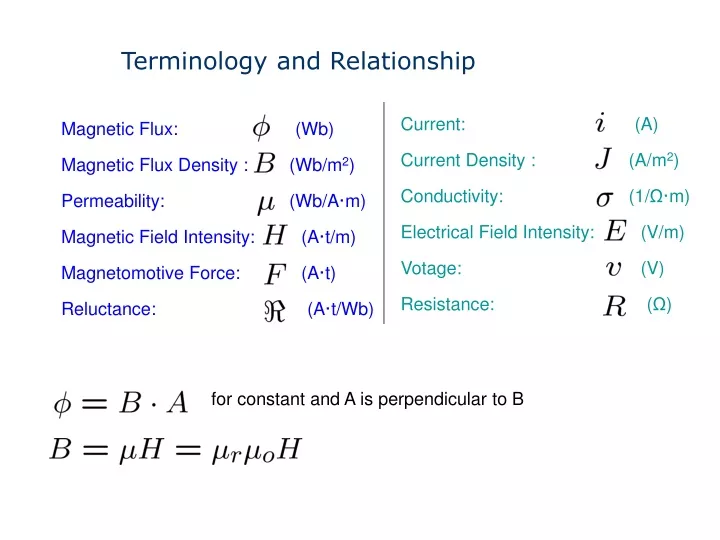
Terminology and Relationship Current: (A) Magnetic Flux: (Wb) Current Density : (A/m2) Magnetic Flux Density : (Wb/m2) Conductivity: (1/Ω·m) Permeability: (Wb/A·m) Electrical Field Intensity: (V/m) Magnetic Field Intensity: (A·t/m) Votage: (V) Magnetomotive Force: (A·t) Resistance: (Ω) Reluctance: (A·t/Wb) for constant and A is perpendicular to B
Terminology and Relationship For a wire carrying a current i, the magnetic field intensity H surrounding the wire is For a coil around a magnetic core, the magnetic field intensity H inside the core is where l is the core mean length
Inductance According to Faraday’s Law: where N is the turns in the coil The total flux is proportional to the current in the coil: Here L is the inductance, and therefore we obtain:
Inductance define reluctance (Final)
Coupled Inductors where k is coupling coefficient and 0≤ k ≤1
Coupled Inductors Apply KVL:
Ideal Transformer For k=1, where n is called turns ratio n=N2/N1
Ideal Transformer For an ideal transformer, it does not dissipate power, therefore the input power should equal the output power: Therefore, the input impedance for the transformer:
Non-Ideal Transformer For a non-ideal transformer, we don’t know whether V1 and I1 in phase or not:
Non-Ideal Transformer When ?
Non-Ideal Transformer When we have