Download
1 / 23
230 likes | 235 Views
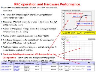
Operation and Performance of HBD in Run- 9. Itzhak Tserruya PHENIX Collaboration Meeting, August 5-7, 2009. Reminder of HBD concept. primary ionization. HV. photo electron. charged particle or photon. HV. primary ionization. ~350nm CsI. signal electron. e -. partner positron

E N D
Operation and Performance of HBD in Run- 9 Itzhak Tserruya PHENIX Collaboration Meeting, August 5-7, 2009 I. Tserruya
Reminder of HBD concept primary ionization HV photo electron charged particle or photon HV primary ionization ~350nm CsI signal electron e- partner positron needed for rejection Cherenkov blobs e+ qpair opening angle ~ 1 m “Traditional”operation Cherenkov detector with a 50 cm long radiator operated with CF4 as radiator and detector gas in a windowlessconfiguration using a triple GEM stack as detector element with a CsI photocathode evaporated on the top face of the top GEM with ~2cm pad readout. Hadron Blind operation RB: drift field repels ionization trail towards the mesh, away from GEM stack, but the strong electric field across the GEMs sucks Cherenkov photo-electrons into the holes FB: electric field drifts ionization trail towards GEM stack
Outline • Detector Operation • Gain determination • Gain monitoring • Reverse bias • Gain stability • Gas transmission monitoring • Detector Performance • Hadron blindness • mip response in forward and reverse bias • e – h separation • electron detection efficiency • single vs double electron separation • combinatorial background rejection • Conclusions and outlook I. Tserruya
HBD performance in Run-9 I. Tserruya
Tracking, matching and alignment • Zero field run. • HBD operated in forward bias mode in order to see MIP distribution. • Reconstructed hadron tracks in central arms projected to HBD. • Each module aligned according to the matching distributions in and z. • Position resolution: • z ≈ ≈ 1 cm • Dictated by pad (hexagon) size: • a = 1.55 cm 2a/√12 = 0.9 cm I. Tserruya
Hadron rejection factor Pulse height Hadron Blindness Hadron suppression illustrated by comparing hadron spectra in FB and RB (same number of central tracks) Pulse height • Strong suppression of hadron signal at reverse drift field • Much larger rejection combining pulse height and cluster size I. Tserruya
Single electron - hadron separation in RB • Runs in (+-) field. • HBD in reverse bias. • Reconstructed tracks in Central Arms are projected to HBD. • Single electrons selected by Dalitz open pairs (m< 150 MeV/c2) • The residual dE/dx charge from hadrons is very small wrt electron response
Single electron detection efficiency 1. Single electron efficiency derived from the 500 GeV +- run using a sample of open Dalitz decays (0.025 < m < 0.050 GeV/c2 where the number of conversions is relatively small and where the combinatorial background is negligible. : ≈ 90 % Similar results obtained from the 200 GeV data 2. Single electron efficiency derived from the J/psi region ( m > 3.5 GeV/c2 after background subtraction): = 90.6 9.9 % I. Tserruya
Single vs double electron separation Fully reconstructed 0Dalitz pairs (m < 150 MeV/c2) in the central arms Matched to HBD into two separate clusters or one single cluster. Single electron response (0Dalitz open pairs) Double electron response (0Dalitz close pairs) I. Tserruya
Combinatorial Background rejection • With the performance results shown in the previous slides we should be very close to the design values for the CB rejection. • **Very** preliminary rejection numbers: • 7.1 2? • ~2. - matching to HBD - double hit cut - close hit cut - single pad cluster cut 6.5 I. Tserruya
HBD operation in Run-9 I. Tserruya
Zoom Gain determination using scintillation hits Method developed in Run-7: exploit scintillation hits (identified as single pad hits not belonging to tracks) to determine the gain on a pad by pad basis. Forward Bias Scintillation Ionization • Gain determination: • Fit scintillation component with an exponential fnct • 1/slope = G . <m> • <m> = avrg nr of scintillation photons in a fired pad) • Assuming the nr of scintillation photons per pad follows a Poisson distribution: • A fired pad measures: • <m> = • P(0) = probability to have no hit in a pad = • <m> = Reverse Bias Scintillation unchanged Ionization suppressed
Gain monitoring and equilibration • Gain monitoring: gain is calculated for each module and each run through on cal. • Gain variations due to p/T changes, automatically compensated by varying the operating HV pre-determined for 5 p/T windows. • Gain equilibration: gain is non-uniform over the GEM area due to variations of the hole diameter coming from the GEM production process. Determine the gain on a pad by pad basis using scintillation hits and apply correction factor to equilibrate the gain to the average value of each module. <G> = Gi/96 ai ai <G> / Gi I. Tserruya
Reverse bias • Hadron signal drops suddenly as drift field goes reverse • Photo-electron signal falls off slowly with increasing reverse field. • Must adjust the drift field as close to zero as possible to avoid unnecessary p.e. losses. • Lengthy and time consuming operation using the mip signal Landau fit I. Tserruya
Adjusting the Reverse Bias using scintillation light • Exploit the scintillation that remains unchanged when switching from FB to RB • Method invented in Run-9 • Very simple, fast and precise ES1 =-10V Red (+5V), black (0V) green(-5V),blue(-10V), rest(-15V and lower) Hits per event Pulse height [ADC counts] I. Tserruya
Gain stability West East I. Tserruya
Run9 Gas Transmittance History • Gas transmittance remained rather stable from the beginning of the run up to about mid-May. • After that, the transmittance for the return gas dropped from about 90 to 80%, reflecting a similar drop in the input gas. • The drop in transmittance is clearly correlated with the Analyzers which also showed increased ppm values of H20 and with the observed drop of N_pe in the data. • The Gas House gets very hot (>100F) in summer time , and as a result Rob P. believes the water scrubber is not doing its job at the elevated temperature. • Rob and Carter are looking into a solution for Run-10. Cooling down the entire GH is not easy since all devices there must be classified at “Class 1, Div.2”.
HV Operation: summary • WEST: • All 10 modules were operated in a very stable mode during the entire duration of the run. • EAST • 8 modules operated in a reasonably stable mode during the entire run • 1 module very unstable (EN4) • 1 module was disabled (ES1) at the beginning of the run due to a short between the mesh and the top GEM. Not clear what happened. • LeCroy HV PS • Problems with one of the LeCroy PS which induced from time to time, in an erratic way, a trip on the quartet of modules that it supplies. Could not replace it due to lack of spares. Should not be an issue for Run-10 I. Tserruya
Resistive Chain Outside HBD =2.2M Inside HBD 28 HV segments in each GEM R2=20M Top GEM =10M Middle GEM Bottom GEM • Operation: VGEM = 500V HV= 3720V I = 150A • Dead short in one GEM: I increases by 1.56%
History of shorts and resistor changes during Run-9 EN4M 1 short known from assembly 3/4/09 WN1T20M (1 short1 strip) ES2B20M (1 short 1 strip) ES3M20M (1 short 1 strip) 3/9/09 ES1 out of commission (1 or 2 shorts + mesh touching top GEM) 3/12/09 EN5B 20M (1 short 1strip) EN4M infinite (2 shorts 2 strips) 4/1/09 EN4B 20M (~complete short at HV, 180M at 0V 1 strip) 5/1/09 EN4B20M (~complete short at HV, 80M at 0V1 strip) 5/12/09 EN4T12M (58M short at HV 1 strip?) EN4M10M ( ~9M at HVpossibly a 3rd partial short? 3 strips? ) EN4B38M (13M short2 strips?) 5/27/09 EN4T20M (20M short at HV1 strip [full short]) EN4Minfinite (~10M short at HV 2 strips [3rd short healed?]) EN4Binfinite (~10M short at HV2 strips [full short]) 6/4/09 ES3B20M (1 short 1 strip) • 7/8/09 • EN2-B 20M --> (1 short 1 strip). This short occurred at precisely the same time the Magnets were ramped on 7/7/09 while the HBD was at standby (2500V) . • EN4-T: 17.6M @500V and 19.5M @450V as of 7/7/09 (New 2nd partial short?) • EN4-M: Had 10M short as of 5/27/09 --> 8.4M as of 7/7/09 (3rd partial short...comes and go. • EN3-T: 2.2G (Fluke), 180M @500V --> NEW SHORT! Due to human error on 7/8/09.
Summary of shorted strips at end of Run-9 (Each GEM (22.1 x 26.8 cm) is segmented into 28 strips narrow in phi (8mm) and long in z ) to reduce its capacity). • West: • one short in one module WN1 0.2 % acceptance loss • East: • ES1 disabled (1/2 in central arm acceptance) 2.6% • ES2 1 shorted strip • ES3 2 shorted strips • EN2 1 shorted strip • EN3 1 shorted strip • EN4 5-7 shorted strips • EN5 1 shorted strip • Total 11-13 strips + ½ of ES1 ~ 5 % acceptance loss Clear difference in the behavior of the West compared to the East reflecting the much better assembly procedure used for the West detector. I. Tserruya
HV operation: conclusions • Overall the detector operated very well during Run-9 • Based on the short history, it is clear that there will be some more degradation during Run-10 if nothing is done, although no one can predict its magnitude. • It is difficult and unpractical to operate a GEM that has more than 2 shorted strips. EN4 is thus very close to be a lost module. • In addition to the acceptance loss, the dead strips induce distortions of the electric field, gain variations and reduced performance in the vicinity of a dead strip. We are trying to assess the effect using the run-9 data but this is a lengthy and not so easy task. . Conclusion: We know what the problem is, it will aggravate if nothing is done, we know how to fix it (the procedure used for the West arm) and we are ready to fix it. I. Tserruya
Towards Run-10 • We propose to fix the East before Run-10, using the experience gained with the fast assembly procedure of the West arm. • Pursue Run-9 data analysis • Use Run-9 data to improve pattern recognition and simulate Au-Au central events • Looking forward to Run-10 I. Tserruya