Download
1 / 17
180 likes | 358 Views
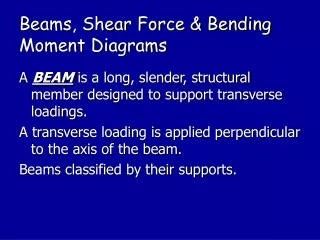
Shear and Moment Diagrams. Today’s Objective : Students will be able to: Derive shear and bending moment diagrams for a loaded beam using a) piecewise analysis b) differential/integral relations. These diagrams plot the internal forces with respect to x along the beam. APPLICATIONS.

E N D
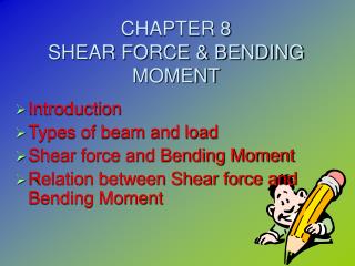
Shear and Moment Diagrams • Today’s Objective: • Students will be able to: • Derive shear and bending moment diagrams for a loaded beam using a) piecewise analysis • b) differential/integral relations
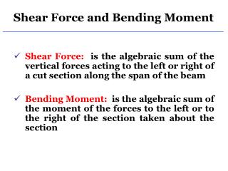
These diagrams plot the internal forces with respect to x along the beam. APPLICATIONS They help engineers analyze where the weak points will be in a member
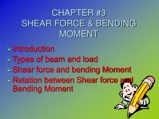
General Technique • Because the shear and bending moment are discontinuous near a concentrated load, they need to be analyzed in segments between discontinuities
Detailed Technique • 1) Determine all reaction forces • 2) Label x starting at left edge • 3) Section the beam at points of discontinuity of load • 4) FBD each section showing V and M in their positive sense • 5) Find V(x), M(x) • 6) Plot the two curves
SIGN CONVENTION FOR SHEAR, BENDING MOMENT Sign convention for: Shear: + rotates section clockwise Moment: + imparts a U shape on section Normal: + creates tension on section (we won't be diagraming nrmal)
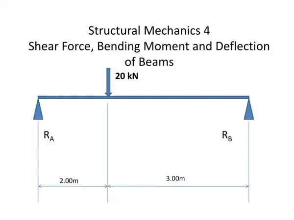
Example • Find Shear and Bending • Moment diagram for the beam • Support A is thrust bearing (Ax, Ay) • Support C is journal bearing (Cy) • PLAN • 1) Find reactions at A and C • 2) FBD a left section ending at x where (0<x<2) • 3) Derive V(x), M(x) • 4) FBD a left section ending at x where (2<x<4) • 5) Derive V(x), M(x) in this region • 6) Plot
Example, (cont) • 1) Reactions on beam • 2) FBD of left section in AB • note sign convention • 3) Solve: V = 2.5 kN M = 2.5x kN-m • 4) FBD of left section ending in BC: • 5) Solve: V = -2.5 kN -2.5x+5(x-2)+M = 0 M = 10 - 2.5x
Example, continued • Now, plot the curves in their valid regions: • Note disconinuities due to mathematical ideals
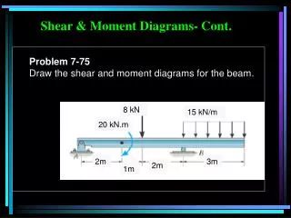
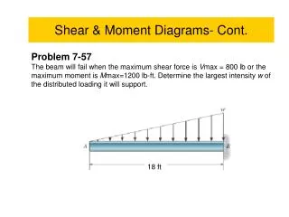
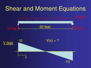
Example2 • Find Shear and Bending • Moment diagram for the beam • PLAN • 1) Find reactions • 2) FBD a left section ending at x, where (0<x<9) • 3) Derive V(x), M(x) • 4) FBD a left section ending somewhere in BC (2<x<4) • 5) Derive V(x), M(x) • 6) Plot
Example2, (cont) • 1) Reactions on beam • 2) FBD of left section • note sign convention • 3) Solve:
Example 2, continued • Plot the curves: • Notice Max M occurs • when V = 0? • could V be the slope of M?
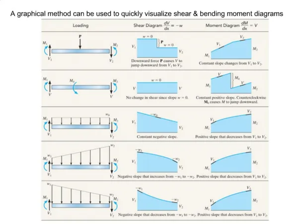
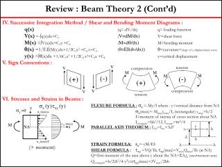
A calculus based approach • Study the curves in the previous slide • Note that • 1) V(x) is the area under the loading curve plus any concentrated forces • 2) M(x) is the area under V(x) • This relationship is proven in your text • when loads get complicated, calculus gets you the diagrams quicker
derivation assumes positive distrib load Examine a diff beam section
Example3 • Reactions at B
End of the Lecture Let Learning Continue

![Shear Force and Bending Moment Diagrams [SFD & BMD]](https://cdn1.slideserve.com/2511906/shear-force-and-bending-moment-diagrams-sfd-bmd-dt.jpg)


![Shear Force and Bending Moment Diagrams [SFD & BMD]](https://cdn3.slideserve.com/6594612/shear-force-and-bending-moment-diagrams-sfd-bmd-dt.jpg)
![Shear Force and Bending Moment Diagrams [SFD & BMD]](https://cdn5.slideserve.com/9656216/shear-force-and-bending-moment-diagrams-sfd-bmd-dt.jpg)