Download
1 / 17
170 likes | 202 Views
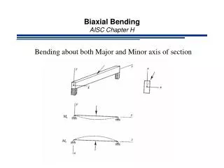
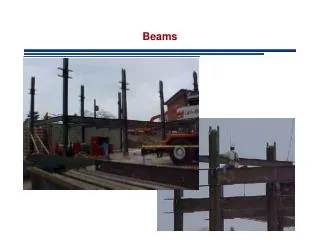
Beams, Shear Force & Bending Moment Diagrams. A BEAM is a long, slender, structural member designed to support transverse loadings. A transverse loading is applied perpendicular to the axis of the beam. Beams classified by their supports. Beams, Shear Force & Bending Moment Diagrams.

E N D
Beams, Shear Force & Bending Moment Diagrams A BEAM is a long, slender, structural member designed to support transverse loadings. A transverse loading is applied perpendicular to the axis of the beam. Beams classified by their supports.
Beams, Shear Force & Bending Moment Diagrams • Shall approach this through examining BEAMs. • There are a number of steps that you MUST go through to get the solution. • Make sure you follow this every time – makes solution a lot easier!
Bending of Beams Many objects in everyday life can be analysed as beams. The design and analysis of any structural member requires knowledge of the internal loadings acting within it, not only when it is in place and subjected to service loads, but also when it is being hoisted. In this lecture we will discuss how engineers determine these loadings. If we ignore mass of the beam, the forces on the beam are as shown: Load Force Support reaction forces. We shall normally ignore the beam mass in these lectures.
Bending of Beams In the figure, the force shown downwards is acting on the beam. It is a point load, acting at a single point on the beam. Load Force Support reaction forces.
Beam loading: Point loading Uniformly Distributed Loading (UDL) UDL e.g. UDL – 20N/m, 3kN/m Combined loading
Example Determine the reactions of a beam of length 4.5 m which is supported at its ends and subject to a point load of 9 kN a distance of 1.5 m from the left-hand end. Neglect the weight of the beam. 9 RB RA The reactions at the supports can be found by taking moments about LHS: MA = 0 = RB 4.5 – 9 1.5 RB = (9 1.5)/4.5 = 3kN Fy = 0 = RB + RA – 9 RA = 6kN
SHEAR FORCE • The algebric sum of the vertical forces on either side of the section of a loaded beam is called Shearing Force
Bending Moment • The algebric sum of the moments of the forces on either side of the section of a loaded beam is called Bending Moment.
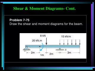
To determine the shear force at 1m from the LHS: Fy = 0 = 360 – 120 – V1 V1 = 240 kN To determine the bending moment at 1m from the LHS: Mat 1m = 0 = -540 + (360 1) - (120 0.5) – M1 M1= - 540 + 360 - 60 = - 240 kNm
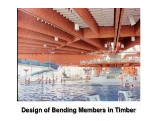
If we wanted to determine the SF and BM at any point along the beam, would need to go through this process each time. • You will agree this tedious. • We need an alternative method to enable us to determine SF and BM at any point along the beam. Shear force and bending moment diagrams. • Shear force diagrams and bending moment diagrams are graphs used to show the variations of the shear forces and bending moments along the length of a beam.
A steel beam 8m long is pin-jointed at the left-hand end and simply supported 4m from the right-hand end. The beam is loaded as shown. For the beam: (a) Determine the reactions at A and C. (b) Derive equations for the shear force and bending moment as a function of distance ‘x’ (horizontal displacement from the left-hand end). (c) Draw the shear force and bending moment diagrams for the beam, and determine the position of counteraflexure (should one exist). 15kN 2kN/m A B C D E 2 1 2 3
(a) Draw the FBD. 2 3 = 6kN 15kN Rax A B C D E 1 Ray Rc By inspection Rax = 0 Have TWO unknowns: Ray and Rc. Therefore, require TWO equations: Fy = 0 & M = 0 Fy = 0 = Ray – 15 + Rc – 6 Ray = 21 - Rc (1) MA = 0 = (15 2) – (Rc 4) + (6 6.5) 30 - 4Rc + 39 = 0 2 Rc = 69/4 = 17.25kN
15kN A B C D E 3.75 17.25 Sub for Rc into equation (1) Ray = 21 - 17.25 = 3.75 kN (b) To derive the equations, split the beam into a number of spans. Start from the LHS and whenever you come across a force OR bending moment, you get a span for which an equation has to be derived. X=4 X=0 X=2 X=5 X=8 Span AB: 0 x 2 Span CD: 4 x 5 Span BC: 2 x 4 Span DE: 5 x 8
CHECK: M = -x2 + 16x -64 M/x = -2x + 16 = Vde
(c) To plot the shear force and bending moment diagrams is now a straight forward process of putting in the limits positions of ‘x’ in each of the equations and plotting the values on a graph.
Point of counterflexure is a point where the bending moment graph crosses the axis. There are situations where there is NO point of counterflexure, i.e. the bending moment graph DOES NOT cross the axis. At the point of counterflexure, the bending moment is EQUAL TO ZERO. In this question we do have point of counterflexure. This occurs over span BC, .i.e. when 2 x 4 Mbc = -11.25x + 30 = 0 x = 30/11.25 = 2.67m The point of counterflexure is when x = 2.67m


![Shear Force and Bending Moment Diagrams [SFD & BMD]](https://cdn1.slideserve.com/2511906/shear-force-and-bending-moment-diagrams-sfd-bmd-dt.jpg)