Download
1 / 45
520 likes | 711 Views
Mobile Positioning E-911 & LBS. Bikash Saha EUS HUB Manager (MPS/LBS) 972.583.5865 bikash.saha@ericsson.com. Agenda. Drivers E-911 Mandate MPS for GSM Positioning Technologies Architecture Ericsson Solution Roadmap Design and Verification Procedure Why Ericsson MPS. Drivers.

E N D
Mobile PositioningE-911 & LBS Bikash Saha EUS HUB Manager (MPS/LBS) 972.583.5865 bikash.saha@ericsson.com
Agenda • Drivers • E-911 Mandate • MPS for GSM • Positioning Technologies • Architecture • Ericsson Solution • Roadmap • Design and Verification Procedure • Why Ericsson MPS
USA’s FCC Regulation: E-911 Ph2 • Wireless Internet
Phase II Accuracy Standards • For Handset-Based Solutions: • 50 meters for 67 percent of Calls • 150 meters for 95 percent of calls • For Network-Based Solutions: • 100 meters for 67 percent of calls • 300 meters for 95 percent of calls
Recent FCC Actions • Request for Relief • Over the past few years, carriers have been asserting the need for relief from E-911 rules • FCC set forth standard for carriers seeking relief: • Plan that is specific, focused, and limited in scope • As close as possible to full compliance • Clear path to full compliance
Recent FCC Actions • Approval of Compliance Plans • 10/5/01: FCC approved, with conditions and modifications, revised implementation plans of five nationwide wireless carrier • Nextel, Sprint, Verizon and GSM portion of AT&T Wireless and Cingular networks • Sixth nationwide carrier VoiceStream had their plan approved year before • Plans contain specific schedules and benchmark • Quarterly reports required to monitor compliance • Move to enforcement mode
Points of Concern • Delay in reaching interim benchmarks towards full compliance. • Some uncertainty about manufacturers producing necessary equipment in timely fashion. • ILEC issues. • Funding for PSAPs. • Still a long road before end-to-end systems are operational throughout the country.
Going forward • The tragedies of September 11 give a new sense of urgency to the rollout of wireless E911. More than ever, mobiles phone have become indispensable tools for calling for help and for delivering help. • The future of location technology is strong • As deployment proceeds, technology and system-wide performance will improve. • Customers increasingly will insist on having it available (like air bags and seatbelts in cars). • Commercial location-based services will add to customer value and carrier revenue • But to get to the future, those involved-- including the FCC-- will have to redouble efforts to see that the promise of this life saving technology is fulfilled
AGPS Yellow Pages Internet API WAP Mobile Network MPC Cell/Sector ID/Timing Advance O/M Center Billing Center Customer Administration Center PSAP E-OTD Mobile Positioning System Overview -GSM
ESNE ESME ALI DB E-911 Phase 2 CAS Push Wireless Emergency Call - GSM S/R LEC MSC Ai,Di PSAP Gateway MLC BSSMAP Complete Layer 3 [CM Service Request] BSSMAP Perform Location Ack BSSMAP Perform Location BSS Serving MLC SMLC determines the positioning method and instigates the messages for the specific positioning method BSSMAP Perform Location BSSMAP Perform Location Ack MS Call Setup IAM [CgPN = callback#, GDP=ESRD, CGL=lat/long CM Service Request
ESNE ESME ALI DB E-911 Phase 2 NCAS Pull Wireless Emergency Call - GSM Initial position already available in GMLC S/R LEC MSC Ai,Di PSAP Gateway MLC BSSMAP Complete Layer 3 [CM Service Request] BSSMAP Perform Location Ack BSSMAP Perform Location MAP Subscriber Location Report MAP Subscriber Location Report Ack BSS Serving MLC SMLC determines the positioning method and instigates the messages for the specific positioning method BSSMAP Perform Location MAP Subscriber Location Report [MSISDN, IMSI, MSC address, ESRD, ESRK, CALL RELEASE] MAP Subscriber Location Report Ack ESPOSREQ [callback# or ESRK, INITIAL] BSSMAP Perform Location Ack esposreq [initial lat/long] MS Call Setup CM Service Request Call Release
SMLC SMLC Other PLMN GMLC GSM LCS Architecture LMU Type A Lp Um Lb(BSS) HLR Ls(NSS) Lh Um Le A Lg Abis MS BTS/LMU B ExternalLCS Client BSC MSC/VLR GatewayMLC Abis Lg LMU Type B
Positioning Methods in GSM • Cell- ID and Timing Advance (CGI+TA) • Network based method • Network Assisted GPS (A-GPS) • Terminal based method • Enhanced Observed Time Difference (E-OTD) • Terminal based method • Uplink Time-Of-Arrival (UL-TOA) • Network based method
Cell-ID and Timing Advance • Based on existing CGI and TA • Default/Fallback Positioning Method • Used to assist other positioning mechanisms • Accuracy depends on cell size and MS distance from cell
LMU LMU E-OTD Time of Arrival information is collected by the MS
LMU LMU E-OTD Real Time Difference information is collected by the LMU Observed Time Difference(OTD) information is collected by the MS
LMU LMU E-OTD Real Time Difference information is collected by the LMU OTD and RTD information is transmitted to the network PLMN Observed Time Difference (OTD) information is collected by the MS
E-OTD MAIN CHARACTERISTICS - + • Only small software modifications in the MS needed • Utilises existing capabilities of the GSM network • Accuracy between 50 and 300 m • LMUs have to be placed between every 1-3 base stations • Cost of network upgrade
A-GPS GPS Assist information collected by the network PLMN
A-GPS GPS Assist information collected by the network Network assist information is transmitted to the MS PLMN
A-GPS GPS Assist information collected by the network Network assist information is transmitted to the MS GPS position fix is determined by the MS (with network assistance) PLMN
A-GPS GPS Assist information collected by the network Network assist information is transmitted to the MS GPS position information is transmitted to the network GPS position fix is determined by the MS (with network assistance) PLMN
Assisted GPS variants • MS based GPS • Give full assistance data to MS • Perform Position calculation in MS • Greater MS complexity • MS assisted GPS • Provide limited assistance data • Return TDOA values • Perform Position calculation in the network • More signaling, no stand-alone position
A-GPS MAIN CHARACTERISTICS - + • Lower power consumption than GPS • Fast Time-To-First-Fix (TFF) • Accuracy down to 10m • Allows for navigation • Limited indoor coverage (GPS has no indoor coverage) • Fall back solutions in comparison to GPS • Additional HW +SW in the MS • A few DGPS reference receivers needed
GPS E-OTD GSM POSITIONING METHODS - RELATIVE ACCURACIES A-GPS CGI. CGI+TA Rural Sub-urban Urban City Indoor 1 3 10 30 100 300 1K 3K 10K 30K Accuracy (meters)
SERVICE DESCRIPTON GMLC PLMN MS MO-LR MT-LR NI-LR MT-LR Mobile Terminating Location Request MO-LR Mobile Originating Location Request NI-LR Network Induced Location Request
MT-LR NI-LR MO-LR Information Tracking Games FriendFinder BikeFinder BrandFinder E911, E112 Dynamic call routing Home Zone Billing Navigation Real time advertisment Radio Network Planning EXAMPLES OF SERVICES
Positioning Methods in UMTS • Cell Id • Cell Id + RTT (Round Trip Time) • OTDOA with/without IPDL • Assisted GPS
E-OTD /// LMUs Type A E-OTD /// LMUs Type A and Type B A-GPS Single Cell TA/ATI GSM 98/99 Compliant BSS-Centric Single Cell TA Ericsson Networks Single Cell TA Single Cell TA MPS-G 5 Lite MPS-G 3.0 MPS-G 4.0 MPS-G 5.0 Full October, 2002 GSM R9.1 In Service GSM R8.0 GA Q2 02 GSM R9.0 GA Q1 02 GSM R9.0 MPS-G Roadmap
Summary of Network Impacts on Positioning Accuracy • Timing delays due to multipath and distributed components • Cell size versus accuracy targets and traffic distribution • Relative base station location and MS-BTS location • BCCH and BSIC planning and adequate C/I(MS & LMU) • Neighbor definitions and positioning considerations • Mobile Station assistance Data
System Prerequisites for E-OTD • Each cell seen by at least 1 LMU • RXLev at LMU Antenna connector >= -110 dBm • C/I at LMU >= 10 dB • C/A (200 kHz) >= -8 dB • C/A (400 kHz) >= -41 dB • Mean excess delay for LMU is assumed to be 0.15 s • GDOP between 1 and 1.5 • BTS coordinates known in three dimensions within 5-10 m
Network Recommendations to Meet Positioning Accuracy Targets Actions will be investigated in order increasing cost and complexity. • BSIC Replanning • BCCH Frequency Plan Retune • Changes to Certain RN Features (HCS, Cell Load Sharing, etc.) • Modifications to existing sites (antennas, output power, etc.) • Site Additions in Certain Areas
SMPC HLR Lb Type A Ls Lh BSC RBS A Lg LMU LMU MSC/ VLR Abis GMPC External LCS client Type B Other PLMN GMPC Core Network Design - GMPC and SMPC Dimensioning
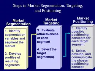
Design and Verification Process INPUT Carrier Input Site Survey, Evaluation & Measurements DESIGN Initial LMU Design and Required Network Changes LMU BTS List 3rd Best Serving Site Coverage Analysis GDOP Analysis Implementation of Network Changes [Carrier Responsibility] Update of LMU Design G/SMPC Dimensioning LMU-A/BTS SMS Dimensioning Parameter Settings Preparation
Not part of design or verification process Involves field work Analysis activities Design and dimensioning activities Design and Verification Process (cont’d) Installation and Integration of Equipment VERIFICATION Positioning Verification Installation and Integration of Additional Equipment [If Necessary] Positioning Re-Verification [If Necessary} Verification Report Acceptance
End-to-end solution Network Applications Consulting / Integration Devices / Design & Verification MPC Systems Terminals and Content !
MPS references • 26 commercial contracts already signed (As of today)) • 4 contracts signed in US from 3 major operators for MPS solution both in • GSM (GMPC, SMPC/PDE, LMU-A/B and SW upgrade for the other nodes in Core network as well as access network) & • TDMA • ~5 trials • ~3 Letters of Intent
Complete Solutions from Ericsson • Location Technology & Roadmap • Mobile Positioning System (TDMA, GSM, UMTS) • Basic and high location accuracy • Roadmap for the future • Presence in all LCS standard activities • Location Based Applications • Ericsson together with Partners • Service Enabling Products • WAP Gateway, Middleware, WAP Application Server, etc. • Services • Design & Verification • Integration, installation, training etc. • Branding, pricing, etc.