Download
1 / 8
80 likes | 178 Views
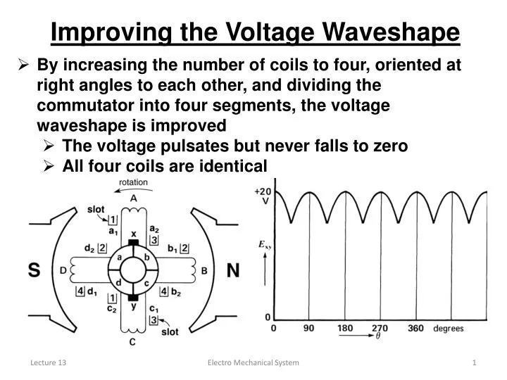
Improving the Voltage Waveshape. By increasing the number of coils to four, oriented at right angles to each other, and dividing the commutator into four segments, the voltage waveshape is improved The voltage pulsates but never falls to zero All four coils are identical.

E N D
Improving the Voltage Waveshape • By increasing the number of coils to four, oriented at right angles to each other, and dividing the commutator into four segments, the voltage waveshape is improved • The voltage pulsates but never falls to zero • All four coils are identical Electro Mechanical System
Improving the Voltage Waveshape • Coils A and C (conversely, B and D) experience the same flux but are traveling in opposite directions • The polarities of ea and ec (eb and ed) are therefore opposite • At all times: ea + eb + ec + ed = 0 , consequently, no current will flow in the closed loop formed by the four coils • The voltage between the brushes varies between ea at 0° and ea+ ed at 45° Electro Mechanical System
Induced Voltage • By increasing the number of coils and commutator segments, the DC voltage waveshape can have smaller ripples • When the coils are rotated, voltage E induced in each conductor depends upon the flux density and the rate at which it cuts: E = Blv • because the cutting of flux density in the air gap varies from point to point, the value of induced voltage per coil depends upon its instantaneous position Electro Mechanical System
Neutral Positions • At times, a brush straddles two commutator segments that are connected to a coil • The brush short-circuits the coil • however, the coil is not cutting through any flux and the induced voltage is momentarily zero • no current will flow through the short-circuit of the brush • Brushes are placed in the neutral position where short circuits occur during momentarily zero induced voltage Electro Mechanical System
Neutral Zones • If the brushes are located away from neutral positions • The voltage between the brushes will decrease • Large short-circuit currents flow at the brushes, causing sparks • Neutral zones are those places on the surface of the armature (rotor) where the cutting of the flux density is zero • At no-load operating conditions, the neutral zones are located exactly half-way between the poles • During loading conditions, armature reaction will cause the neutral zones to shift away from the half-way point Electro Mechanical System
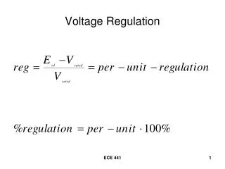
Calculating the Induced Voltage • The peak voltage, EO, induced between the brushes in a DC generator having a lap winding is given by • EO = Zn / 60 • where • Z = total number of conductors on the armature • n = speed of rotation [rpm] • = flux per pole [Wb] • Example • The armature of a 6-pole, 600 rpm generator has 90 slots each coil has 4 turns and the flux per pole is 0.04 Wb • calculate the value of the induced voltage • Z= 90 coilsx 4turns /coil x 2conductors / turn= 720 • EO = Zn / 60 = (720 x 600 x 0.04)/60 = 288 V Electro Mechanical System
Generator under Load • Under loading conditions, some fundamental flux and current relationships take place that are directly related to the mechanical-electrical energy conversion process • The current delivered by the generator also flows through all the armature conductors • The current carrying conductors are subjected to a force according to Lorentz’s law • The forces on each conductor result in a torque that acts opposite to the direction of rotation (counter-torque) Electro Mechanical System
Generator under Load • To keep the armature of the generator turning in the given direction of rotation • A torque must be applied to the shaft to overcome the opposing electromagnetic torque (the drive torque) • The resulting mechanical power is converted into electrical power that is delivered to the load Electro Mechanical System