Download

1 / 29
290 likes | 410 Views
CMS Global Calorimeter Trigger Hardware Design. 21/9/06. CMS Level-1 Trigger. Position of the Global Calorimeter Trigger in The CMS Level-1 Trigger system. RCT Data Output. 18 RCT Crates cover CMS Calorimeter barrel Each Crate covers 0.7 Φ x 5 η region

E N D
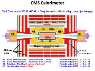
CMS Level-1 Trigger Position of the Global Calorimeter Trigger in The CMS Level-1 Trigger system
RCT Data Output • 18 RCT Crates cover CMS Calorimeter barrel • Each Crate covers 0.7 Φx 5 η region • Outputs Electron and Jet Information to GCT η -5 0 5 0 0 9 1 10 Φ 2 11 3 12 π 4 13 5 14 6 15 7 16 8 17 2π
GCT Requirements • Sorts Electrons • 4 highest Energy • Finds and sorts Jets • Top 4 by energy, physical size, tau … • Sorting criteria may be changed • Sort by energy for initial implementation • Algorithm implements 3x3 sliding window • Requires contiguous data space – spans RCT crate boundaries • Data sharing scheme needs to be implemented • This algorithm drives processing requirements • Processes data at ~250 Gbps • Latency requirement of 24 bunch crossings • 600 nS • Interfaces to 18 RCT crates • 108, 68 pin parallel cables • Differential ECL, not DC balanced • Need to maintain ground reference with entire RCT • Entire row of racks on different floor
Jet finder • Parallel algorithm implements 3x3 sliding window over each RCT crate’s data space • Overlaps neighboring crates • RCT data must be shared between Instances • Instances must be in close proximity • Same Device if possible • High bandwidth connection if not • Note overlap at η0 • Data duplicated • Sent to both jet finders • Poster covers this subject in detail Jet finder 1 Jet finder 2 Jet finder 3 η -5 0 5 0 0 9 Φ 1 10 “Revised CMS Global Calorimeter Trigger Functionality & Performance” 2 11 3 12 π 4 13 5 14
Design Tradeoffs • Design on a compressed schedule • Reduce risk to the extent possible • Base on existing modules • Conservative data rates • Minimize number of FPGAs • Reduce firmware risk • Never split algorithms • Algorithm size and complexity drives FPGA selection • Easier simulation • Better synthesis efficiency • Superior timing (and lower overall power consumption) • Judicious use of serializer/deserializers • Most efficient method of concentrating data • Latency penalty of at least 6 clocks • Only use on system boundaries • RCT/GCT • GCT/GT • Significant negative impact on complexity of design • Several cards used mainly as “signal plumbing”
Design Overview • Three main elements • Data transport and physical concentration • Trigger processing • Data plumbing and sorting • Data Transport • Compress RCT data and provide electrical isolation • Functionally part of the RCT • What we really wanted it’s output to be • Trigger Processing • Implement Jet finders • Modular processing element • Data Plumbing • Large, physically complex boards • Required to deal with multiple wide parallel busses • Excellent example of why SERDES technology was developed • Unfortunately required due to latency constraints
Design Overview • Modular design with 4 card types • Source card (based on Imperial College IDAQ VME module) • Serializes RCT data and transmits on fiber • Electrically isolates GCT from RCT • Reduces interface cabling, allows physical data concentration • Resides in RCT racks • Also provides RCT readout • Leaf card (based on Los Alamos digital channelizer double PMC) • Jet processing and fiber receiver • Logic capacity driven by Jet finder algorithm • Also used for Electron sort • Wheel card (new CERN design) • Only used for Jet processing • Carries multiple Leaf cards • Facilitates Leaf data sharing • Sorts resulting Jets • Concentrator card (new CERN Design) • Electron and final Jet sort • Carrier Leaf cards for Electron sort • Interfaces with Wheel cards for final jet sort • Slow control, TTC, and DAQ interface
GCT Block Diagram 63 source cards (not shown) 8 Leaf cards 2 Wheel cards 1 Concentrator Leaf Card Concentrator card Wheel Card
Electrical Interfaces • LVDS signaling • Used between Leaf cards, and from Wheel to Concentrator • Cable based board/board connections • 40MHz DDR required, but can support faster • Direct FPGA drive in most cases • Direct connections provide maximum flexibility and speed • Wheel/Concentrator Jet data passes through single ended/diff converters • Pin limits due to large number of signals • Samtec QTS/H differential connectors • High density and speed, Rated for multi GHz operation • Commercial cable assemblies • DDR used for all single ended I/O • FPGA intercommunication at 40MHz • Short runs allow faster operation • Communication with Leaf cards at 40MHz • PMC connectors limit speed here • Leaf cards utilize 2.5V LVCMOS with DCI (nominally 50 ohms at this point) • Single ended outputs from FPGAs utilize DCI drivers • Allow controlled impedance drive • Nominally 50 ohms at this point
Clock Distribution 4x4 Cross point switch 4x4 Cross point switch Concentrator Wheel Fan out Fan out 40MHz 80MHz 160MHz 40MHz 80MHz 40MHz from Concentrator TTCrx QPLL QPLL PMC sites Wheel cards Local FPGAs PMC sites Local FPGAs External Input 80MHz from Concentrator FPGA Control FPGA Control • Fully differential distribution tree • Controlled by cross point switches • Allows stand alone operation • Use DLLs in FPGAs to tune if necessary 4x4 Cross point switch Leaf Fan out Local 80MHz reference 80MHz FPGA SERDES ref OSC External input FPGA Logic clocks 40, 80MHz from Wheel FPGA Control
JTAG System Concentrator Wheel Board header Board header To wheel Front panel Board header From concentrator CPLD JTAG Samtec differential Connector/cable CPLD JTAG Samtec differential Connector/cable J T A G J T A G Differential buffers Differential buffers VME S W I T C H E S 2, 3.3V JTAG chains JTAG SWITCH (CPLD) JTAG SWITCH (CPLD) 6, 2.5V JTAG chains 6, 2.5V JTAG chains JTAG Mode S W I T C H E S 2, 3.3V JTAG chains JTAG Mode JTAG CPLD is a combinatorial flow-through design A single chain, or multiple chains (daisy chained) are selected via front manual mode switches JTAG source is either header or remote device, selected by mode switch Leaf JTAG is single chain (4 devices)
Source Card • Based in IDAQ module designed at Imperial College • Simplified due to large number required for complete system • Converts ECL RCT input to SFP optical • Two VHDCI SCSI inputs, 32 bits at 80MHz • Four SFP fiber outputs • Spartan 3 • 4 SERDES/SFP modules • 8b/10b encoding • DC balanced • 1.6Gbps • Comma generation (sync) • TTCrx • Time synchronization • USB slow control • Provides RCT readback
6 Block diagram • 10 layer PCB • USB slow control • TTCrx and QPLL • VHDCI SCSI inputs • Serial SPF outputs • Agilent HFBR-5720AL • TLK2501 SERDES • Rated at 2.5 Gbps • Linear power for SERDES/SFP • Switching power for FPGA • Spartan3 FPGA • 3S1000 4 7 4 1 2 8 3 5
Leaf Card • Based on satellite channelizer design at Los Alamos Lab • Modified to include V2Pro and MFP connectors • Main processing engine of GCT • Accepts Jet data from 3 RCT crates • Electron data from 9 RCT crates • 32 fiber optic links • SNAP-12 MFP optics • Rated at 2.5 Gbps • Jet algorithm drives capacity • 3M gates/jet finder • 10 fibers/crate • 2 V2Pro70 FPGAs
Block Diagram • Clock Distribution • Local oscillator • PMC/coax inputs • PMC connectors • 8 fully populated • 60 pair differential links • Switching power supplies • 1.5V core and 2.5V I/O • Phase and freq controlled • Linear SERDES supplies • 12 channel optical receivers • Agilent AFBR-742B • 14 layer PCB 3 4 7 V2P70 6 5 6 2 1 4 V2P70 5 6 4 3
Implementation • High density Optical Inputs • Cannot fit enough SFP single channel modules • “Snap 12” parallel receiver • 12 channels at 2.5Gbps • Industry standard short distance link • Xilinx Embedded SERDES links (Rocket I/O) • Virtex2 Pro devices selected • V2P70 with 16 links each • Support improved differential I/O • Easily obtainable • No external (off FPGA chip) memory • Nice to have, but not required for GCT processing • Double PMC format • Power supply and basic layout retained from existing design • Electrically compatible, but too high mechanically • Not truly PMC compliant
Routing Parameters • Length matching • Differential lines matched to ¼” as a bus • Yields ½” on board/board connections • Individual pairs matched to a few mils • Matched in groups of 8 pairs • Not required for 40MHz DDR • Allows significant speed increase • Single ended lines matched to ½” as a bus • Matched in groups of 8-12 lines • Not required for 40MHz DDR • Allows higher speed operation • Differential SERDES lines matched to 1-2 mils • Impedance controlled and individually matched • Board structure isolates SERDES with ground planes • 50 Ohm stripline
Power supplies • 15A, 1.5V switcher for each V2Pro VccInt • Devices can be run at thermal limit • Fan headers on board if needed • Estimated load less than 1/2 this figure • 40MHz, 100% utilization yields 6A • Single 15A, 2.5V switcher for I/O • Estimated load is ½ of this capacity • Switchers powered from 5V • Not used for other logic • Phase and frequency controlled • Can optimize noise or efficiency • Switch out of phase to control surge currents • Separate linear supplies for SERDES • Each FPGA has local linear SERDES supply • Optical receivers powered directly from 3.3V PMC power • Manufacturer claims this is acceptable
Wheel Card • Carries 3 leaf cards (double PMC) • Compresses (sorts) Jet data • Calculates Et and Jet count • Single ended electrical interface (DDR 40MHz) • Interfaces to concentrator board • High speed cable interface • LVDS electrical interface • DDR 40Mhz required, but could support higher • 9U VME form factor • Power only, no VME interface • ECAL backplane
Block Diagram Finished Jet data Energy Sum Data J1 Leaf (x3) J 13 J 14 Diff Buffers Slow control and readback J 11 J 12 J2 Jet FPGA Energy FPGA J 23 J 24 J3 Diff Buffers J 21 J 22
Implementation • Accepts parallel data from leafs on 3 DPMC sites • 278 signals on each site (total 834) • 186 signals/site to Jet FPGA, 92/site to Energy FPGA • Single ended • Outputs parallel data • Electrical interface • 240 differential pairs provided • Processing • Two Xilinx Virtex4 FPGAs • XC4VLX100FF1513 • I/O (as opposed to logic) intensive design • Advanced Virtex4 I/O features reduce risk • Better double data rate support • Improved Differential support • One for Jet sorting, one for Et and Jet count • Jet FPGA pin limited • Requires single ended output to meet signal count • External differential buffers drive data to concentrator
Power supplies • 10A, 1.2V switcher for each V4 VccInt • Devices can be run near thermal limit • Estimated load less than 1/2 this figure at 40MHz • Two 10A, 2.5V switchers for I/O • Leaf cards may be jumpered to provide own VIO • Wheel will only need to drive own FPGAs • 10A, 3.3V switcher for each DPMC site • Board design allows for substitution of 5A Linear • Would be preferable since optical receivers are powered directly • Questionable margin requires switcher site be provided • All Switchers powered from 5V • Not used for other logic • Separate linear supply for QPLL and some clock distribution • 2.5V
Carries 2 Leaf cards (double PMC) Sorts Electron data Single ended 40 MHz DDR interface Interfaces to two Wheel cards Sorts Jet data Differential 40 MHz DDR cable interface Provides VME Interface Slow control and readback TTC interface Timing and synchronization DAQ Interface Slink Carries GT interface PMC 9U VME form factor ECAL backplane Complex design Significant Data plumbing Congested routing Multiple communication Interfaces Concentrator
Block Diagram Leaf PMC x2 J1 P1 Electron FPGA (4VLX100) VME/DAQ FPGA (2V3000) J2 P2 TTC GT Output PMC Jet FPGA (4VLX100) J3 ECAL Slink Carrier P3 Differential connectors To Wheel (x2) VME connectors To backplane VME bus Jet data DAQ data Electron data Jet count/ total Et Slow control/ readback GT output
Processing Two Xilinx Virtex4 FPGAs XC4VLX100-FF1513 Must concentrate large amount of data Choose package with most I/O Integrated differential termination makes layout simpler High speed I/O provide reserve capability Communication Xilinx Virtex2 FPGA XC2V3000-BF957 Robust in 3.3V enviroment VME 64x interface Slink TTCrx Electron FPGA Isolated Electrons Non-Isolated Electrons Energy Sums Jet Counts Jet FPGA Forward Jets Central Jets Tau Jets Power Supplies Identical to Wheel Number and Type Implementation
Status • Schedule Requirements • Concentrator, 2 Leafs, and 7 source cards by 1/07 • Full system by 7/07 • Source card • First articles in hand • Extensively tested, awaiting integration with leaf • Leaf card • First articles in hand • Testing underway • SERDES tests to begin the first week of October • Concentrator card • In production • First articles due in mid October • Wheel card • In final Layout • Production order to be placed by mid October