Download
1 / 19
190 likes | 196 Views
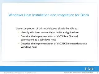
This article discusses the process of integrating subblocks into hard macros and the productization of hard macros in chip design, including physical design, verification, model development, and documentation.

E N D
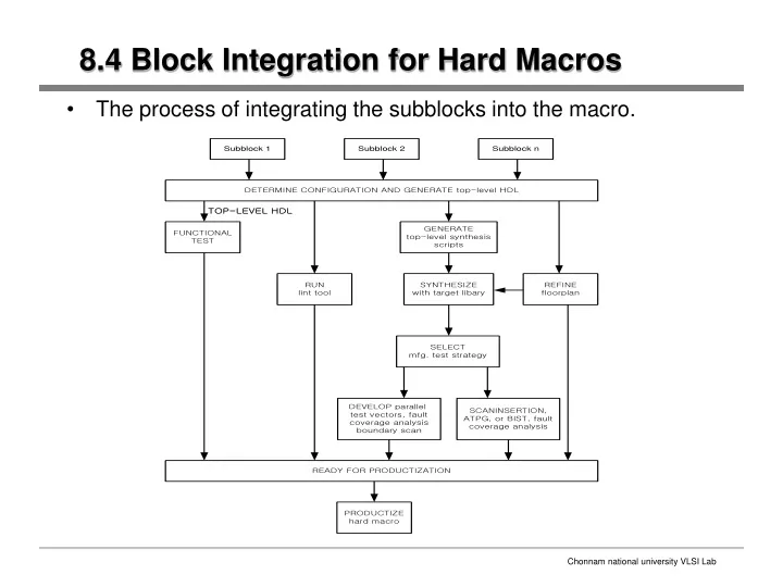
8.4 Block Integration for Hard Macros • The process of integrating the subblocks into the macro.
8.4 Block Integration for Hard Macros[cont’d] • Hard macro is available only in a signal configuration. • Functional test is somewhat simplified; no multiple-configuration testing is required, as it is for soft macros. • Synthesis is needs to target only the technology library. Because porting is done at the physical level, after synthesis, there is no requirement to produce optimal netlists in a variety of technologies. • Synthesis of the macro is an iterative process that involves refining the floorplan based in synthesis results
8.5 Productization of hard Macros • Productizing hard macros
8.5.1 Physical Design • The basic loop of floorplanning and incremental synthesis, place and route, and timing extraction. • In the first pass of this loop, the final floorplan and synthesized netlist provide the inputs to the place and route tools. • One key to successful physical design is to have a high quality cell library. The library should have been fully characterized to ensure theat the timing models are accurate. • The library should also have all the views required to complete the design, including power modeling.
8.5.2 Verification • Gate verification • We use formal verification to prove that the final gate-level netlist is equivalent to the RTL. For hand-crafted block, we use a combination of LVS(Layout vs, Schematic), to verify transistor to gate netlist equivalence, and formal verification. • Static Timing Analtsis • We perform a final static timing analysis to verify that the design meets timing. • Physical Verification • We use LVS and DRC(Design Rule Checking) tools verify the correctness of the final physical design. The DRC and LVS decks are an important consideration in physical design • These decks need to be consistent between all the block in a chip design.
8.5.3 Models • In addition to the physical design database, we need to develop the models that the integrator will use to model the macro in the system design; • The functional simulation model is developed from the final RTL. • The floorplan model is developed as part if the floorplanning process. • The timing model is developed using the extracted timing values.
8.5.4 Decumentation • In addition to the requirements for a soft macro, the documentation for a hard macro includes: • Footprint and size of the macro • Detailed timing and power specification • Routing restrictions and porosity • Power and ground interconnect guidelines • Clock and reset timing guidelines
8.6 Model Development for Hard Macros • For most hard macros, the desired models include; • Behavioral or ISA model for fast simulation • Bus functional model for assisting system-level verification • Full functional, cycle-accurate model for accurate simulation • Timing model; this model is required to perform full-chip timing analysis. • Floorplaning model for physical design • Functional model for emulaton
8.6.1 Functional Models • Model Security • One of the critical issues in developing a modeling process is determining the level of security required for the models. • An RTL wrapper is used to provide a simple timing and functional interfaces to the RTL for the rest of the chip. By delivering object, the designer ensures a high level of escurity • Behavioral and ISA Models • Extensive hardware/software cosimulation is critical to the success of many SoC design project • Behavioral and ISA models provide very high performance models for large system block by abstracting out many of the implementation details of the design • This model accurately reflects the instruction level behavior of the process while abstracting out implementation details • This high level model is referred to as an ISA or ISS
8.6.1 Functional Models[cont’d] • The SoC design can then use the ISA model to verify the software and the rest of the system design • The hardware/software cosimulation environment provides an interface between this model and the RTL simulation of the rest of the hardware Fig 1-1. Hardware/software cosimulation using an ISA model
8.6.1 Functional Models[cont’d] • Behavioral models are the equivalent of ISA models for non-processor designs. • Behavioral models can be written in C/C++, Verilog, or VHDL, and they may be protected or unprotected. • Behavioral models can also be written using the new testbench generation tools VERA and Specman Elite • A substantially equivalent flow is possible with Visual IP • VMC compiles the Verilog model and the simulation kernel into a VCS compatible abject format • VFM then adds the SWIFT interface, allowing the model to work with all major simulators
8.6.1 Functional Models[cont’d] • Bus Functional Models • Bus functional models abstract out all the internal behavior of the macro and only provide the capability of creating transactions on the output buses of the macro. • Bus functional models have usually been developed in Verilog of VHDL, and distributed in source code. • Full Functional Models • Abstract models are useful for system-level verification, final verification of the RTL must be done using full functional models for all blocks in the design • The RTL for the macro is a full functional model, and is the easiest full function model to deliver to the integrator. • The major problem with full functional models is that they are slow to simulate
8.6.1 Functional Models[cont’d] • Generating full functional models
8.6.1 Functional Models[cont’d] • Full Functional Models with Timing • It is necessary to provide a full functional model that contains detailed timing ingormation. Fig 1-2. Generating full functional models with timing
8.6.1 Functional Models[cont’d] • The timing information for these buffers can be derived from the extracted timing information from place and route. • This approach can be very effective provided that the macro is designed so that it does not have state dependent timing. • Emulation models • Emulation is one approach to addressing the problem of slow system-level simulation with full functional models. • Emulation requires that the model for the macro be compiled into a gate-level representation. • Hardware models • Hardware models provide an alternate approach for providing highly secure full functional models. • Hardware models are system that allow a physical device to interface directly to a software simulator.
8.6.2 Synthesis and Floorplanning Models • The timing and floorplanning models can be generated from the design database. • The final place and route of the macro, we can extract the basic blockage information, pin locations, and pin layers the macro. this information can then used by the integrator when floorplan- ning the SoC design. Fig 1-3. Generating static timing models for standard cell designs • This model provides the setup • and hold time requirements • For input pins and the clock- • to-output delay for the output • pins • This model is delivered as a • Synopsys standard format.
8.6.2 Synthesis and Floorplanning Models[cont’d] Fig 1-4. Generating static timing models for full custom designs • After parasitic extraction, • the CoreMill static timing • analysis tool verifies that • the timing requirements • for the design are met. • Prime Time uses this • Stamp model to develop • the final timing model in • the . db format.
8.7 Porting Hard Macros The porting strategy is quite straigtforward for hard IP • Automated porting Automatically mapping transistors and interconnect from one set of design rules to another, and shrinking the design as much as possible. • Problem -> clocking and hold time. As the technology shrinkings, circuits speed up, and the acceptable clock skew becomes smaller, and minimum delays from flop to flop become less.